
Intercepting method for gas gushing out during tunnel construction

A tunnel construction and gas technology, applied in tunnels, gas discharge, earthwork drilling and mining, etc., can solve problems such as gas gushing out, affecting the construction period, and reducing the tunneling speed of the face

Active Publication Date: 2018-05-08
CHINA RAILWAY 23RD CONSTR BUREAU LTD +1
View PDF6 Cites 2 Cited by
  • Summary
  • Abstract
  • Description
  • Claims
  • Application Information

AI Technical Summary

Problems solved by technology

[0002] Gas gushing out of the rock body is often encountered during tunnel excavation construction, which can easily cause safety accidents. Therefore, gas drainage in tunnel excavation is a very important task. The existing method is to detect excessive gas concentration in advance at the face of tunnel excavation When drainage is required, drain holes are made on the face of the face, and then the gas gushing out of the holes is sucked by the suction device to reduce the gas concentration in the face area so that the gas concentration does not affect the gas concentration of the face. Normal excavation. Although this method can make the tunnel face safe excavation, it greatly reduces the excavation speed of the tunnel face and affects the construction period.

Method used


Image

  • Intercepting method for gas gushing out during tunnel construction
  • Intercepting method for gas gushing out during tunnel construction
  • Intercepting method for gas gushing out during tunnel construction

Examples


Embodiment

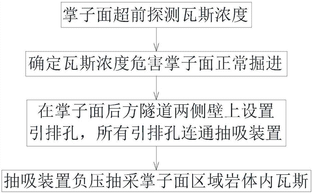
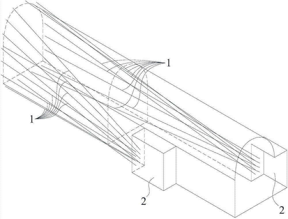
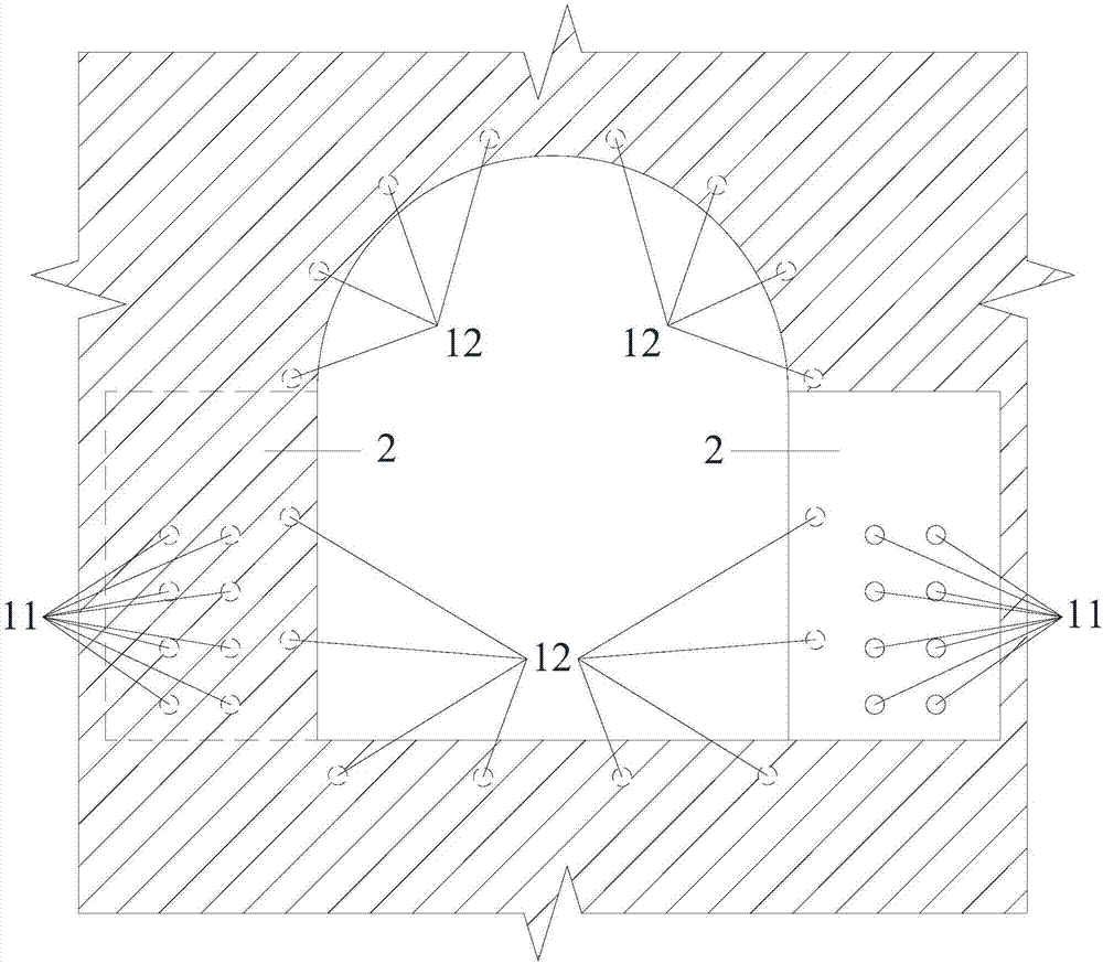
[0036] Such as Figure 1-3 Shown, a kind of tunnel construction gushing gas interception method described in the present invention comprises the following steps:

[0037] A. Advance detection of gas concentration on the face of tunnel excavation;

[0038] B. Guide the tunnel construction according to the real-time value of the gas concentration in step A, until the tunnel face advances in gas concentration and endangers the normal excavation work of the tunnel face;

[0039] C. Set 16 drainage holes 1 with a diameter of 108mm on both side walls of the tunnel 10m behind the tunnel face, and each drainage hole 1 extends along the tunnel excavation direction to the rock mass ahead of the tunnel face, and The end points 12 of all the drainage holes 1 are arranged along the periphery of the tunnel, and the starting points 11 of all the drainage holes 1 are connected to the suction device;

[0040] D. The suction device extracts the gas in the rock body in the face area under nega...


PUM


Abstract

The invention discloses an intercepting method for gas gushing out during tunnel construction. The intercepting method comprises the following steps that A, advanced detection of the gas concentrationof a tunnel face is conducted; B, the situation that the advanced gas concentration of the tunnel face endangers normal driving of the tunnel face is determined; C, a plurality of exhaust guiding holes are formed in the positions, 5-40 m behind the tunnel face, of the two side walls of a tunnel correspondingly, each exhaust guiding hole extends into the part, ahead of the tunnel face, of a rock mass in the tunnel driving direction, all the end points of the exhaust guiding holes are arranged along the periphery of the tunnel, and all the start points of the exhaust guiding holes communicate with a suction device; and D, the suction device sucks the gas in the part, in the tunnel face area, of the rock mass under the negative pressure. By applying the intercepting method for the gas, the exhaust guiding holes are formed in the positions, behind the tunnel face, of the two side walls of the tunnel and extend into the parts, ahead of the tunnel face, of the rock mass, and all the end points of the exhaust guiding holes are arranged on the outline periphery of the to-be-driven tunnel in an enveloping mode so that protection of the upper portion, the lower portion, the left portion andthe right portion of the tunnel can be formed, suction is well conducted accordingly, and the situation that the gas gushes out abnormally, and a safety accident occurs consequently is prevented; andall the exhaust guiding holes for suction are not located in the tunnel face, so that normal driving of the tunnel face is not affected.

Description

technical field [0001] The invention relates to the field of tunnel construction, in particular to a method for intercepting gas gushing out from tunnel construction. Background technique [0002] Gas gushing out of the rock body is often encountered during tunnel excavation construction, which can easily cause safety accidents. Therefore, gas drainage in tunnel excavation is a very important task. The existing method is to detect excessive gas concentration in advance at the face of tunnel excavation When drainage is required, drain holes are made on the face of the face, and then the gas gushing out of the holes is sucked by the suction device to reduce the gas concentration in the face area so that the gas concentration does not affect the gas concentration of the face. For normal excavation, although this method can make the tunnel face safe excavation, it greatly reduces the excavation speed of the tunnel face and affects the construction period. Contents of the inven...

Claims


Application Information

Patent Timeline
Patent Type & Authority Applications(China)
IPC IPC(8): E21F7/00E21D9/14
CPCE21D9/14E21F7/00
Inventor 张义君谢高英李辉奚成王兆丰刘延龙王红亮
Owner CHINA RAILWAY 23RD CONSTR BUREAU LTD
Learn More