Stacking method

A stacking and hopper technology, applied in the field of loading and unloading, can solve problems such as increasing equipment wear, increasing equipment maintenance workload, and reducing equipment operating life.

Inactive Publication Date: 2018-05-11
TIDFORE HEAVY IND
View PDF5 Cites 0 Cited by
  • Summary
  • Abstract
  • Description
  • Claims
  • Application Information

AI Technical Summary

Problems solved by technology

[0002] In the stacking process of the storage yard, the maximum stacking capacity is usually designed, and then the unloading member of the stacking device is fixed at the apex of the maximum stacking capacity for unloading. After the unloading is completed, the scraper machine takes the material; but Often the incoming material in the storage yard is not the designed maximum stacking capacity, or the material needs to be taken out if the maximum storage capacity is not reached, or some materials need to be taken away before the maximum storage capacity is reached, such as Figure 5-7 At this time, the stockpile cannot completely fill the stockyard with materials, and the stockpile type is not close to the discharge port. When the reclaimer starts to work, the working surface at the bottom cannot touch the stockpile, and part of the scraped materials cannot be scraped. After being picked up by the system belt conveyor and transported away, it can only be transferred to the discharge port in the material yard, and there is a problem of doing virtual work. This process is called flat material in the industry. This process is time-consuming, energy-consuming, waste of manpower, and increases Equipment wear and tear, reducing the operating life of equipment and increasing the workload of equipment maintenance

Method used


Image

  • Stacking method
  • Stacking method
  • Stacking method

Examples


Embodiment Construction

[0038] The present invention will be described in detail below in conjunction with the accompanying drawings. The description in this part is only exemplary and explanatory, and should not have any limiting effect on the protection scope of the present invention. In addition, those skilled in the art can make corresponding combinations of features in the embodiments in this document and in different embodiments according to the descriptions in this document.

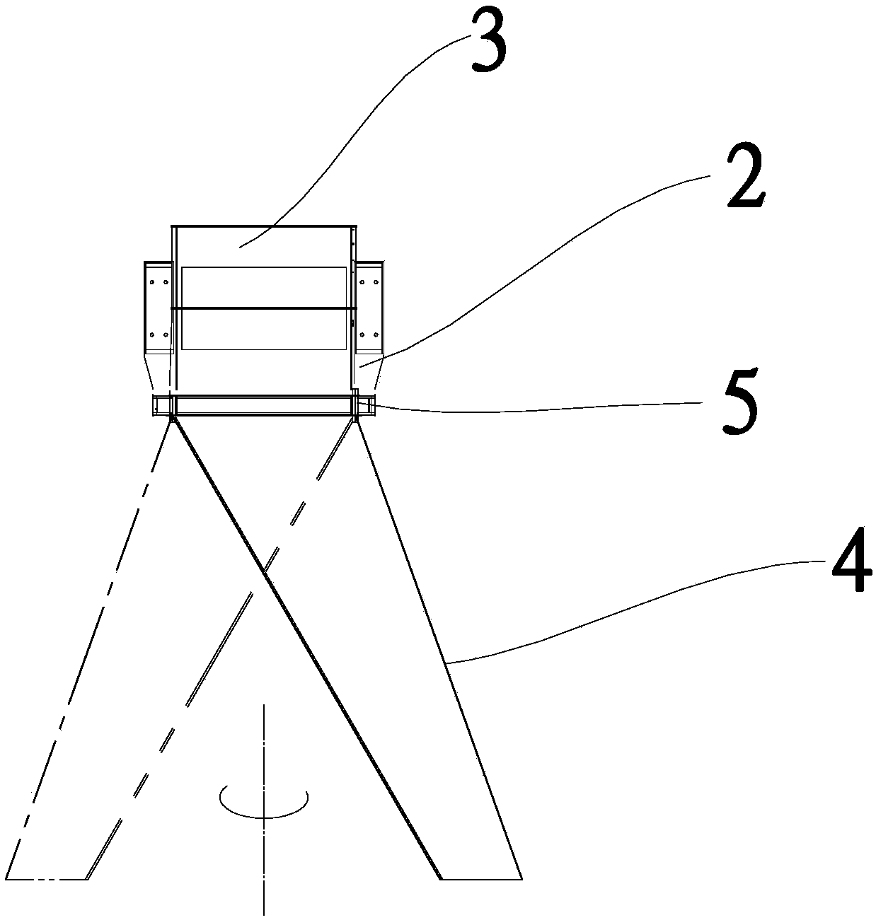
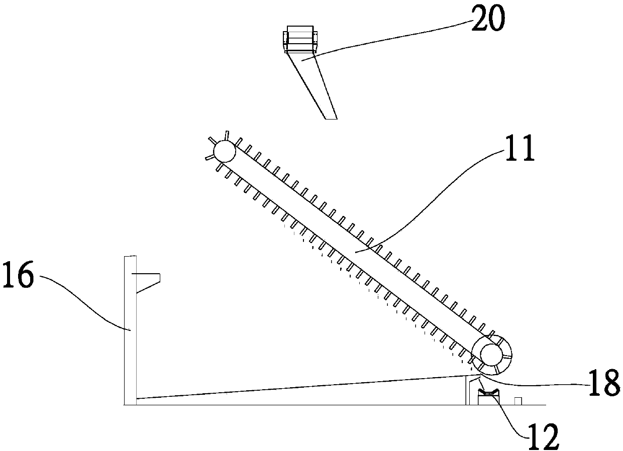
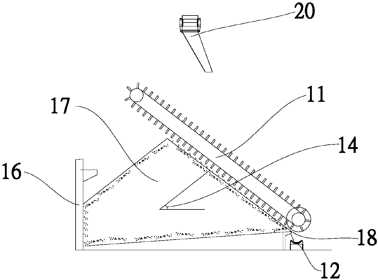
[0039] Embodiments of the present invention are as follows, as Figure 1~4 and Figure 8 , a stacking method, the unloading mechanism 20 of the stacking device includes a hopper body 2, the top of the hopper body 2 is provided with a feed port 3, and the bottom of the hopper body 2 is provided with a blanking chute 4, so The bottom of the discharge chute 4 is provided with a discharge port, the discharge chute 4 can rotate along the hopper body 2 and drive the discharge port to rotate in a horizontal plane, and the stac...


PUM


Abstract

The invention relates to a stacking method which comprises the following steps: (1) determining the optimal unloading point; (2) locating an unloading point of an unloading mechanism of a stacking device at the optical unloading point; and (3) enabling the stacking device to perform stacking operation till the current stacking operation is completed. By adoption of the stacking method for the stacking operation, the optimal unloading point can be calculated according to the stacking operation volume when incoming materials are not insufficient during the stacking process; when the premise of stacking is met, the shape of a stack can be close to a discharging port; when a scraper reclaiming mechanism starts working, materials on an unloading surface can be reclaimed to the bottom of a reclaiming surface, dropped to a material conveying device from the discharging port, and then sent out; during the work of the scraper reclaiming mechanism, an operating surface at the bottom of the scraper reclaiming mechanism can be in contact with the stack; the problem about virtual work can be solved; and accordingly, the operating efficiency during the reclaiming process can be greatly improved,the reclaiming efficiency of the scraper reclaiming mechanism can be improved, the energy consumption can be lowered, the equipment abrasion can be reduced, the equipment operating life can be prolonged, the equipment maintenance workload can be reduced, and the use cost of a factory can be reduced.

Description

technical field [0001] The invention belongs to the technical field of loading and unloading, and in particular relates to a stacking method. Background technique [0002] In the stacking process of the storage yard, the maximum stacking capacity is usually designed, and then the unloading member of the stacking device is fixed at the apex of the maximum stacking capacity for unloading. After the unloading is completed, the scraper machine takes the material; but Often the incoming material in the storage yard is not the designed maximum stacking capacity, or the material needs to be taken out if the maximum storage capacity is not reached, or some materials need to be taken away before the maximum storage capacity is reached, such as Figure 5-7 At this time, the stockpile cannot completely fill the stockyard with materials, and the stockpile type is not close to the discharge port. When the reclaimer starts to work, the working surface at the bottom cannot touch the stockpi...

Claims


Application Information

Patent Timeline
Patent Type & Authority Applications(China)
IPC IPC(8): B65G65/00B65G65/06B65G65/40B65G69/00
CPCB65G65/005B65G65/06B65G65/40B65G69/00
Inventor 孟庆耀冯苹
Owner TIDFORE HEAVY IND
Why Eureka
Try Eureka