
Zero return control method and system of worktable

A control method and workbench technology, applied in the direction of electric speed/acceleration control, etc., can solve the problems of single zero return mode, inability to cope with precise zero return requirements, and insufficient integration.

Inactive Publication Date: 2018-05-11
SHENZHEN CITY SAMKOON TECH
View PDF4 Cites 3 Cited by
  • Summary
  • Abstract
  • Description
  • Claims
  • Application Information

AI Technical Summary

Problems solved by technology

Since the workbench may be at any point in the stroke, and the error between the zero return position and the preset position is required to be within a certain range, the current zero return motion scheme requires the user to manually control to ensure that the initial position of the workbench is within a specific area. It can realize zero return, and the mode of zero return is single, the degree of integration is not high enough, and it cannot meet the requirements of precise zero return in different situations

Method used


Image

  • Zero return control method and system of worktable
  • Zero return control method and system of worktable
  • Zero return control method and system of worktable

Examples


Embodiment Construction

[0073] It should be noted that, in the case of no conflict, the embodiments in the present application and the features in the embodiments can be combined with each other.

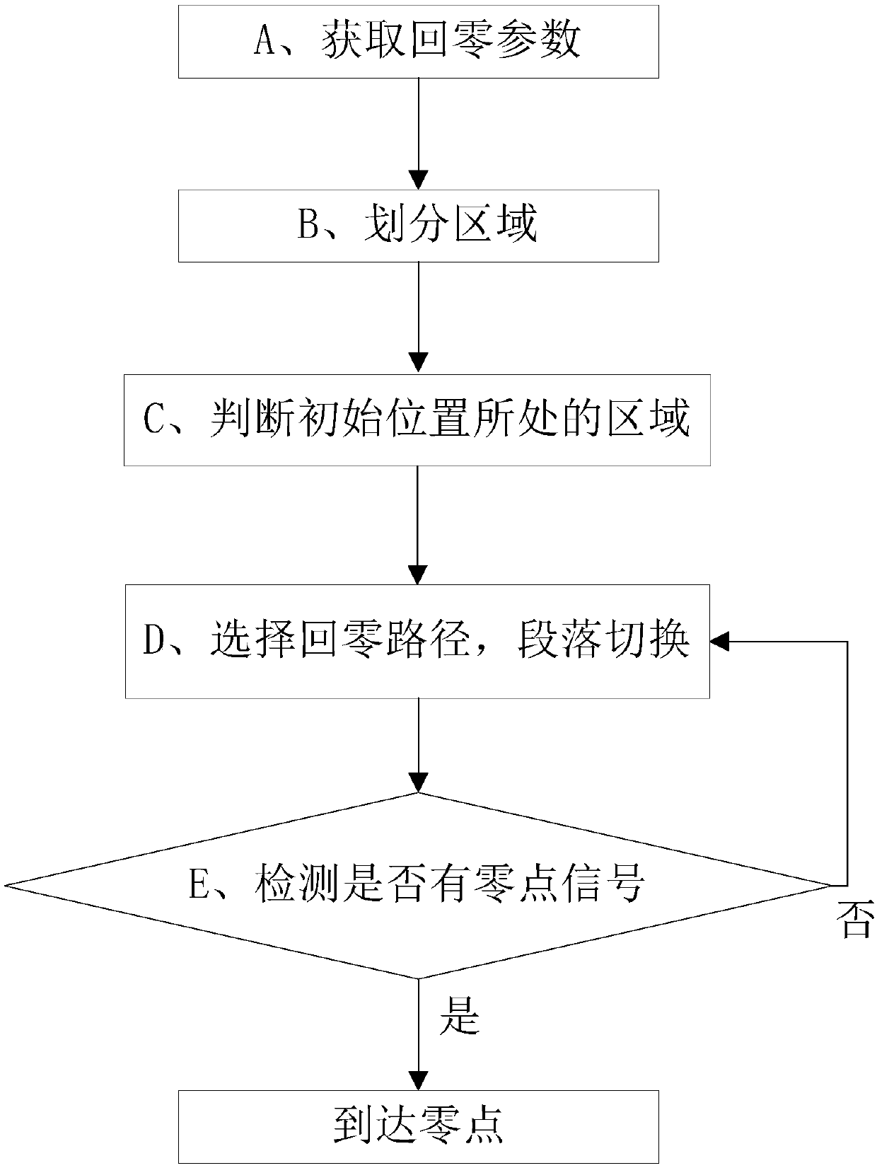
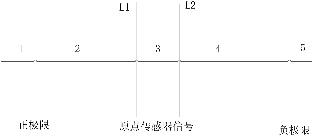
[0074] Based on the existing zero return control scheme, there is a technical problem that the user must manually control to ensure that the initial position of the workbench is in a specific area before the zero return can be realized, which is not only time-consuming and laborious, but also has strong limitations. Therefore, the present invention proposes a A technical solution for solving the above-mentioned technical problems, the basic concept of which is: according to the positive and negative limit signals and the origin sensor signal, the motion plane where the workbench is located (ie the stroke of the workbench) is divided into regions, and then the region corresponding to the position of the workbench is obtained , and then control the workbench to return from the area where it is located to the ...


PUM


Abstract

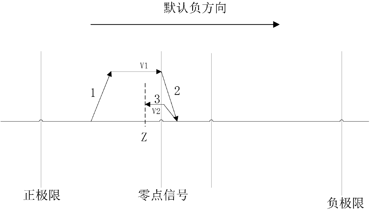
The invention discloses a zero return control method and system of a worktable. According to a zero return parameter, the stroke of a worktable is divided into five regions and a region in which an initial location of the worktable is located is determined; the worktable is controlled to return to a positive side or negative side of a signal range of an original point sensor from the located region; and then the worktable is controlled to return to a zero-point position from the positive side or negative side of the signal range of the original point sensor. Compared with the prior art, random-point zero returning of the worktable is realized.

Description

technical field [0001] The invention relates to the field of workbench control, in particular to a method and system for controlling workbench return to zero. Background technique [0002] ZRNR: Arbitrary point zero point return command [0003] Return speed: high-speed movement starting from returning to zero [0004] Crawling speed: low-speed movement after approaching zero [0005] Near-point signal and zero-point signal: two signal edges will be generated when the worktable moves through the signal range of the origin sensor, one as the near-point signal and the other as the zero-point signal. [0006] Positive limit signal: the signal sent by the positive limit sensor when the worktable moves to the limit position in the positive direction. [0007] Negative limit signal: the signal sent by the negative limit sensor when the workbench moves to the limit position in the negative direction. [0008] Z-phase signal: a pulse sent from a fixed position on the encoder dis...

Claims


Application Information

Patent Timeline
Patent Type & Authority Applications(China)
IPC IPC(8): G05D13/62
CPCG05D13/62
Inventor 宋斌陈泽宇
Owner SHENZHEN CITY SAMKOON TECH
Learn More