
Calculation method for transient stability evaluation index of system after multi-loop DC commutation failure

A calculation method and evaluation index technology, applied in power transmission AC networks, measuring devices, instruments, etc., can solve problems such as difficulty in quantitative calculation, inability to provide quantitative evaluation indicators, poor adaptability to high-power tie lines, etc., and achieve deceleration. area reduction effect

Inactive Publication Date: 2018-05-11
NORTHEAST DIANLI UNIVERSITY +3
View PDF2 Cites 11 Cited by
  • Summary
  • Abstract
  • Description
  • Claims
  • Application Information

AI Technical Summary

Problems solved by technology

At present, the research on this fault form is mainly divided into two-machine cluster method and three-machine cluster method. [5-7] : The two-machine cluster method is to analyze the stability mechanism and influencing factors by equating the actual system to be analyzed into a two-machine cluster system. The actual system can be equivalent to a two-machine cluster system by the equal-area rule to analyze the stability damage caused by DC commutation failure stabilization mechanism [5] , the stability mechanism can be analyzed intuitively from the physical essence, but it is difficult to realize the quantitative calculation of complex systems, and the second-order linear system shock response model is easy to quantitative calculation [6] , but it cannot explain the nature of stability and the poor adaptability to high-power conditions of the tie line; in order to describe the complex state of the actual sending-end system, the "Sanhua" system is equivalent to a three-machine cluster system [7] , which can better interpret the stability mechanism of the stability failure of the sending system caused by the failure of the receiving system. However, the existing literature on the three-machine cluster system focuses on the analysis of the mechanism of the stability failure, and is not perfect in the calculation of quantitative evaluation indicators. Quantitative evaluation indicators cannot be given, so the quantitative calculation still needs to be further improved

Method used


Image

  • Calculation method for transient stability evaluation index of system after multi-loop DC commutation failure
  • Calculation method for transient stability evaluation index of system after multi-loop DC commutation failure
  • Calculation method for transient stability evaluation index of system after multi-loop DC commutation failure

Examples


Embodiment 1

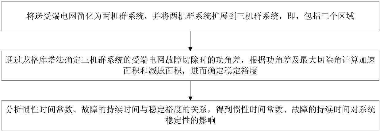
[0041] A calculation method for the transient stability evaluation index of the system after multiple DC commutation failures, see figure 1 , the calculation method includes the following steps:

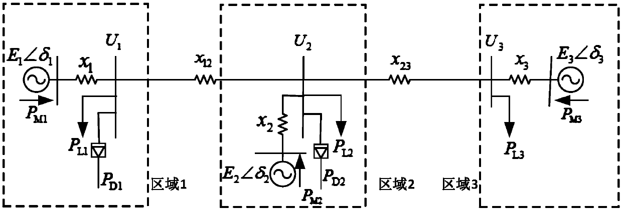
[0042] 101: Simplify the sending and receiving end power grid into a two-machine cluster system, and extend the two-machine cluster system to a three-machine cluster system, that is, including three regions;

[0043] 102: Use the Runge-Kutta method to determine the power angle difference of the receiving end power grid fault removal of the three-unit system, calculate the acceleration area and deceleration area according to the power angle difference and the maximum removal angle, and then determine the stability margin;

[0044] 103: Analyze the relationship between inertial time constant, fault duration and stability margin, and obtain the influence of inertial time constant and fault duration on system stability.

[0045] Wherein, in step 101, the power grid at the sending and re...

Embodiment 2

[0059] Combined with the specific calculation formula, Figure 1-Figure 6 1. Examples further introduce the scheme in Example 1, see the following description for details:

[0060] 201: Simplify the power grid at the sending and receiving end to a two-cluster system, and expand the two-cluster system to a three-cluster system;

[0061] Wherein, the step 201 is specifically:

[0062] 1) Simplify the sending and receiving end power grid into a second-order model of the two-machine cluster system, and obtain the motion equation of the relative speed of the rotor;

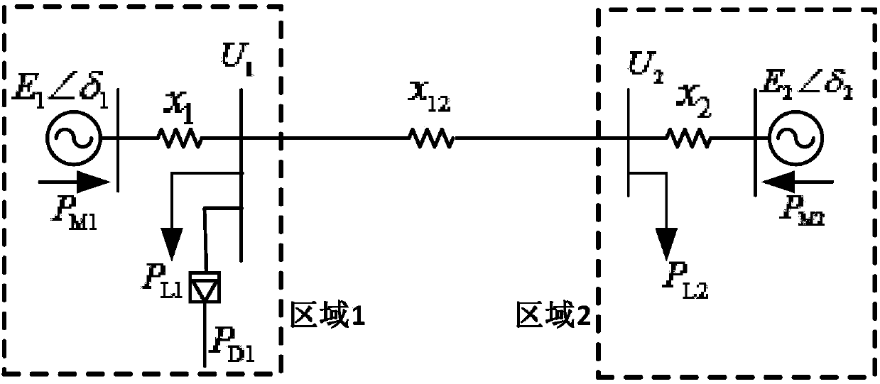
[0063] In the actual power system, in order to facilitate the analysis of the physical nature of the stability problem, the power grid at the sending and receiving end is simplified as figure 1 Two-fleet system shown.

[0064] figure 2 Among them, areas 1 and 2 are equivalent sending-end systems and receiving-end systems, E 1 ,E 2 is the equivalent generator internal potential of the sending-end and receiving-en...

Embodiment 3

[0132] Below in conjunction with specific experimental data, table 1-table 4, carry out feasibility verification to the scheme in embodiment 1 and 2, see the following description for details:

[0133] 1. Analyze the transient stability of the two-machine system

[0134] Using the PSD-BPA developed by China Electric Power Research Institute as the simulation program (this simulation program is well known to those skilled in the art, and the embodiment of the present invention will not repeat this), a three-phase short-circuit fault occurs in the receiving end system, causing DC P D1 When commutation failure occurs, the stability of the power system has two states: system stability and system instability. System stability refers to the maximum relative power angle difference Δδ of all generators after the fault max max ≥360°, analyze the influence of moment of inertia and fault duration on system stability.

[0135] (1) Influence of unit inertia time constant on transient stab...


PUM


Abstract

The invention discloses a calculation method for a transient stability evaluation index of a system after a multi-loop DC commutation failure, and the method comprises the following steps: simplifyingsending and receiving grids into a double-cluster system, and extending the double-cluster system into a three-cluster system which comprises three regions; determining a power angle difference through a Runge-Kutta method during the removing of a fault of the receiving end grid of the three-cluster system, calculating the speed-up area and slow-down area according to the power angle difference and a maximum cutting angle, and determining the stability margin. The method also comprises the steps: analyzing the relation among an inertia time constant, a fault duration time and the stability margin, and obtaining the impact on the stability of a system from the inertia time constant and the fault duration time. According to the invention, the double-cluster system is extended into the three-cluster system, and the extreme cutting angle is determined through the Runge-Kutta method. The stability margin of a power system is calculated, and various demands of actual application are met.

Description

technical field [0001] The invention relates to the field of electrical engineering, in particular to a method for calculating transient stability evaluation indexes of a system after multi-circuit DC commutation fails. Background technique [0002] In recent years, in my country's North China Power Grid and Northwest Power Grid, the installed capacity of wind power and photovoltaics has increased rapidly, which has enabled my country to gradually promote the transmission of power from west to east and build a number of UHV DC lines. , Fufeng 3 circuits of ±800kV UHV DC to the East China Power Grid of the load center, there are 4 circuits of ±500kV UHV DC to the East China Power Grid of the load center, and the total power of the 7 circuits of DC reaches 31760MW [1] . According to my country's power grid planning, in recent years, multiple circuits of UHV DC will be put into operation in Jinbei-Nanjing, Ximeng-Taizhou, Lingzhou-Shaoxing, Zhundong-Wannan, etc. [2-3] . The c...

Claims


Application Information

Patent Timeline
Patent Type & Authority Applications(China)
IPC IPC(8): H02J3/36G01R31/08
CPCG01R31/088H02J3/36Y02E60/60
Inventor 陈厚合屠竞哲张赫王长江姜涛张健贾俊川刘宇石顾卓远于强
Owner NORTHEAST DIANLI UNIVERSITY
Learn More