Motor rotor and permanent magnet motor

一种电机转子、永磁体的技术,应用在磁路、电气元件、机电装置等方向,能够解决永磁电机难以兼顾高频和低频效率、限制电机最高运行频率、降低电机运行效率等问题,达到降低充退磁难度、减小充退磁电流大小、电机运行效率最优的效果

Pending Publication Date: 2018-05-11
GREE ELECTRIC APPLIANCES INC
View PDF6 Cites 22 Cited by
  • Summary
  • Abstract
  • Description
  • Claims
  • Application Information

AI Technical Summary

Problems solved by technology

[0002] Traditional permanent magnet motors rely on permanent magnets to provide magnetic flux, but permanent magnets provide a fixed magnetic field, and the internal magnetic field of the motor is difficult to adjust, making it difficult for permanent magnet motors to take into account the efficiency of high frequency and low frequency
And when the power supply voltage is fixed, the maximum operating frequency of the motor is limited
At present, most permanent magnet motors can only expand the operating range through field-weakening control. When the motor is under field-increasing control, the operating efficiency of the motor will be reduced

Method used


Image

  • Motor rotor and permanent magnet motor
  • Motor rotor and permanent magnet motor
  • Motor rotor and permanent magnet motor

Examples


Embodiment Construction

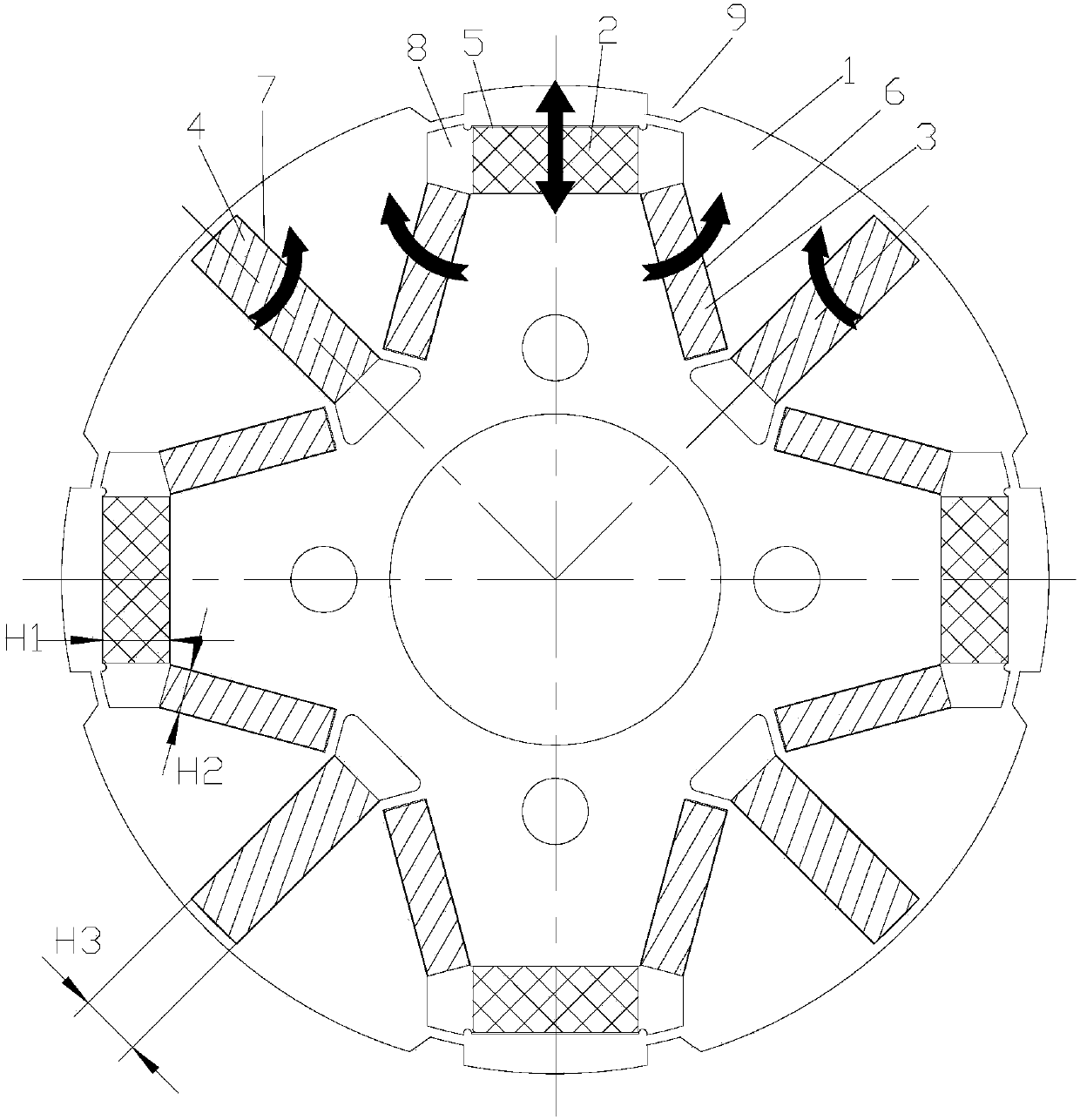
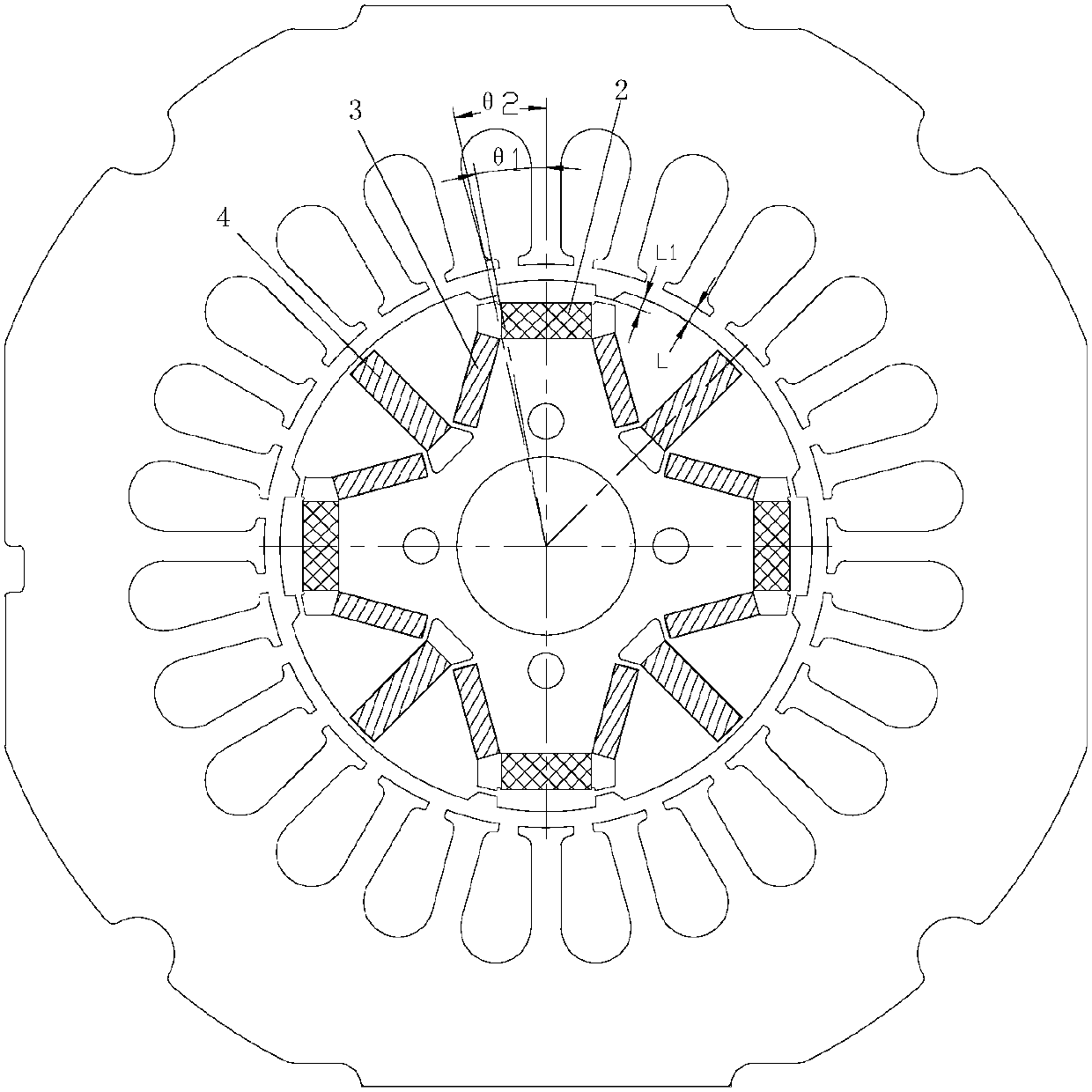
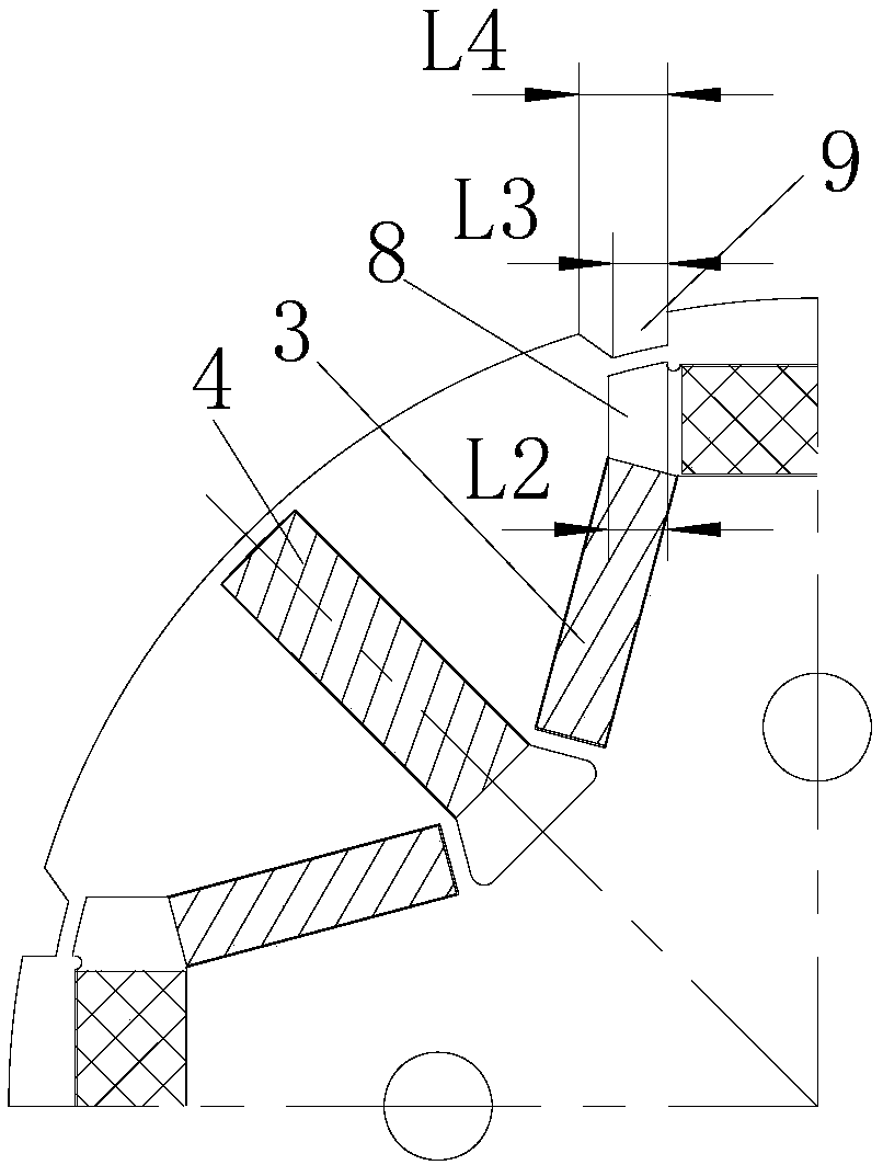
[0039] see in conjunction Figures 1 to 12 As shown, according to the embodiment of the present invention, the motor rotor includes a rotor core 1 and a plurality of magnetic poles arranged in the rotor core 1, and the magnetic poles include a first permanent magnet 2, a second permanent magnet 3 and a third permanent magnet 4, The first permanent magnet 2 is arranged on the central position of its magnetic pole, the second permanent magnet 3 is arranged on both sides of the first permanent magnet 2, and the third permanent magnet 4 is arranged on one side of the second permanent magnet 3 away from the first permanent magnet 2. On the side, the coercive force of the first permanent magnet 2 is smaller than the coercive force of the second permanent magnet 3 and the coercive force of the third permanent magnet 4, and the third permanent magnet 4 is arranged on the q-axis of the motor.

[0040]When the motor rotor is running, the motor control strategy adopts magnetization contr...


PUM


Abstract

The invention provides a motor rotor and a permanent magnet motor. The motor rotor comprises a rotor core (1) and a plurality of magnetic poles arranged in the rotor core (1), wherein each magnetic pole comprises a first permanent magnet (2), second permanent magnets (3) and third permanent magnets (4); each first permanent magnet (2) is arranged at the central position of the corresponding magnetic pole on which the first permanent magnet is located; the second permanent magnets (3) are arranged at two sides of each first permanent magnet (2); each third permanent magnet (4) is arranged at one side, far away from the first permanent magnet (2), of the corresponding second permanent magnet (3); the coercivity of the first permanent magnets (2) is smaller than that of the second permanent magnets (3) and that of the third permanent magnets (4); and each third permanent magnet (4) is arranged on a q axis of the motor. According to the motor rotor, the magnetization and demagnetization difficulties can be effectively reduced, the adjustable flux range of the motor is increased, and the operating efficiency of the motor during magnetization control is improved.

Description

technical field [0001] The invention belongs to the technical field of motors, and in particular relates to a motor rotor and a permanent magnet motor. Background technique [0002] Traditional permanent magnet motors rely on permanent magnets to provide magnetic flux, but permanent magnets provide a fixed magnetic field, and the internal magnetic field of the motor is difficult to adjust, making it difficult for permanent magnet motors to take into account the efficiency at high and low frequencies. And in the case of a fixed power supply voltage, the maximum operating frequency of the motor is limited. At present, most permanent magnet motors can only expand the operating range through field-weakening control. When the motor is under field-increasing control, the operating efficiency of the motor will be reduced. Contents of the invention [0003] Therefore, the technical problem to be solved by the present invention is to provide a motor rotor and a permanent magnet mo...

Claims


Application Information

Patent Timeline
Patent Type & Authority Applications(China)
IPC IPC(8): H02K1/27
CPCH02K1/2766H02K2213/03H02K2201/03H02K3/487
Inventor 胡余生陈彬周博王敏肖勇
Owner GREE ELECTRIC APPLIANCES INC
Why Eureka
Try Eureka