Motor rotor and permanent magnet motor

A technology of motor rotors and permanent magnets, applied in magnetic circuits, electrical components, electromechanical devices, etc., can solve the problems of reducing the operating efficiency of motors, limiting the maximum operating frequency of motors, and the difficulty of balancing high-frequency and low-frequency efficiencies with permanent magnet motors

Active Publication Date: 2018-05-04
GREE ELECTRIC APPLIANCES INC
View PDF4 Cites 6 Cited by
  • Summary
  • Abstract
  • Description
  • Claims
  • Application Information

AI Technical Summary

Problems solved by technology

[0002] Traditional permanent magnet motors rely on permanent magnets to provide magnetic flux, but permanent magnets provide a fixed magnetic field, and the internal magnetic field of the motor is difficult to adjust, making it difficult for permanent magnet motors to take into account the efficiency of high frequency and low frequency
And when the power supply voltage is fixed, the maximum operating frequency of the motor is limited
At present, most permanent magnet motors can only expand the operating range through field-weakening control. When the motor is under field-increasing control, the operating efficiency of the motor will be reduced

Method used


Image

  • Motor rotor and permanent magnet motor
  • Motor rotor and permanent magnet motor
  • Motor rotor and permanent magnet motor

Examples


Embodiment Construction

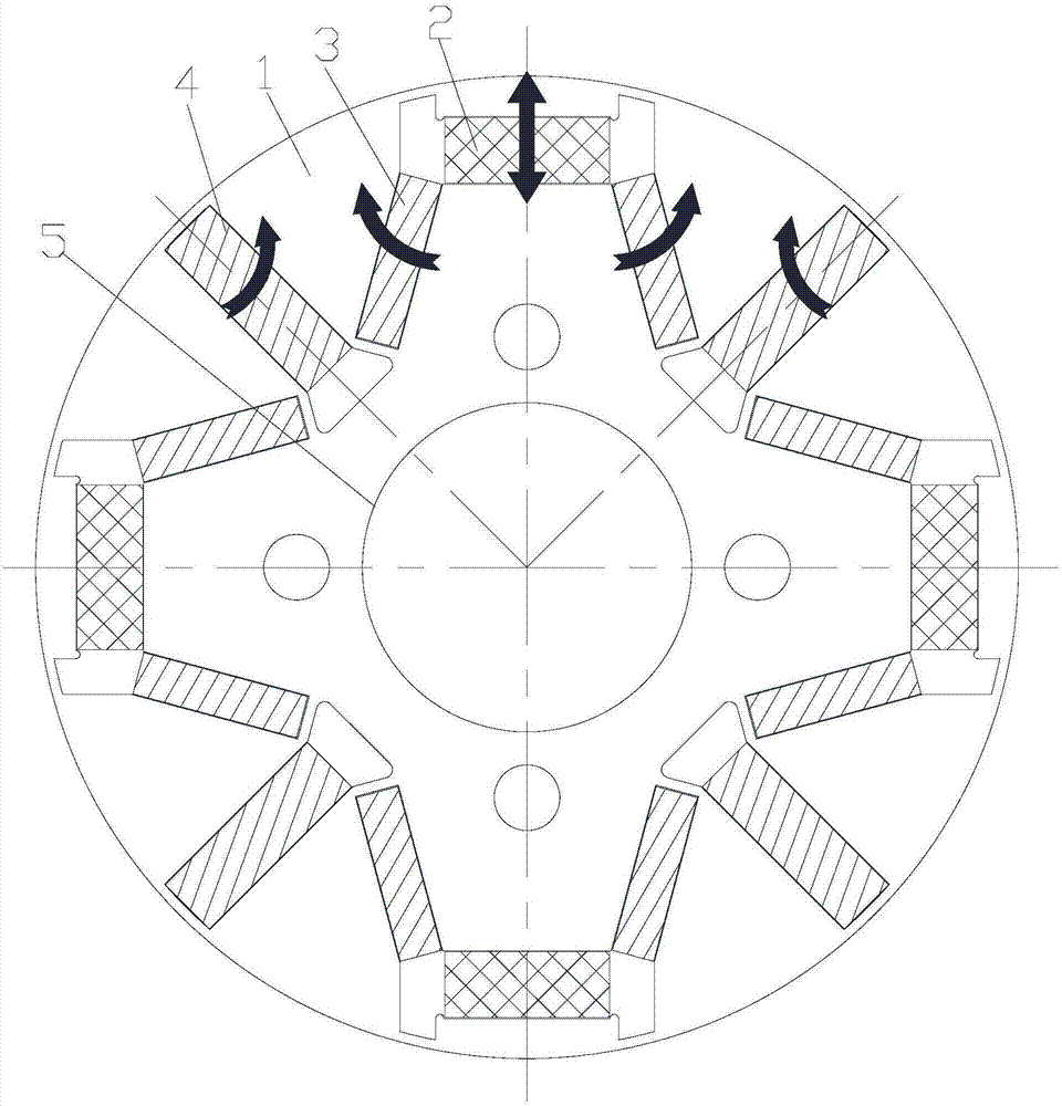
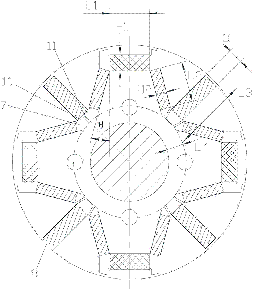
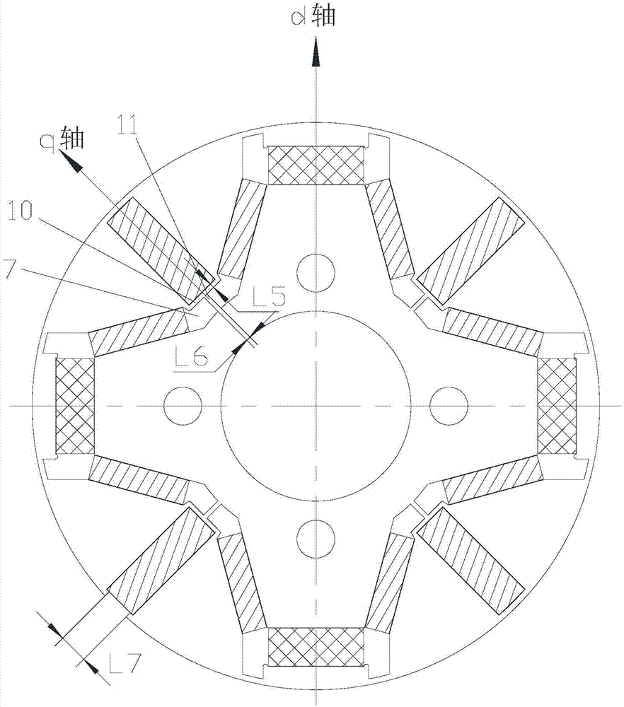
[0023] See also Figure 1 to 4 As shown, according to the embodiment of the present invention, the motor rotor includes a rotor core 1 and a plurality of magnetic poles arranged in the rotor core 1. The magnetic poles include a first permanent magnet 2, a second permanent magnet 3, and a third permanent magnet 4. The first permanent magnet 2 is arranged at the center of its magnetic pole, the second permanent magnet 3 is arranged on both sides of the first permanent magnet 2, and the third permanent magnet 4 is arranged on a side of the second permanent magnet 3 away from the first permanent magnet 2. On the other hand, the coercivity of the first permanent magnet 2 is smaller than the coercivity of the second permanent magnet 3 and the third permanent magnet 4. The third permanent magnet 4 is arranged on the q-axis of the motor on the cross section of the rotor core 1, The dimensional relationship between the first permanent magnet 2, the second permanent magnet 3 and the thir...


PUM


Abstract

The invention provides a motor rotor and a permanent magnet motor. The motor rotor comprises a rotor core and a plurality of magnetic poles arranged in the rotor core, each magnetic pole comprises a first permanent magnet, a second permanent magnet and a third permanent magnet, and the dimension relation of the first permanent magnet, the second permanent magnet and the third permanent magnet on the cross section of the rotor core meets m / 2>H1*Hcj1*L1 / [(H2*Hcj2*L2+1 / 2H3*Hcj2*L3)]>m / 10; wherein m is a multiple of the motor magnetism adjustment range, L1 is the length of the first permanent magnet, H1 is the width of the first permanent magnet, Hcj1 is the intrinsic coercive force of the first permanent magnet, L2 is the length of the second permanent magnet, H2 is the width of the second permanent magnet, Hcj2 is the intrinsic coercive force of the second permanent magnet, L3 is the length of the third permanent magnet, H3 is the width of the third permanent magnet, and Hcj3 is the intrinsic coercive force of the third permanent magnet. According to the motor rotor, the magnetizing and demagnetizing difficulty can be effectively reduced, the motor adjustment range is increased, andthe operation efficiency of the motor in magnetizing control is improved.

Description

Technical field [0001] The invention belongs to the technical field of motors, and specifically relates to a motor rotor and a permanent magnet motor. Background technique [0002] Traditional permanent magnet motors rely on permanent magnets to provide magnetic flux, but permanent magnets provide magnetic field fixation, and the internal magnetic field of the motor is difficult to adjust, making it difficult for permanent magnet motors to take into account the efficiency of high frequency and low frequency. And in the case of a fixed power supply voltage, the maximum operating frequency of the motor is limited. At present, most permanent magnet motors can only expand the operating range through field weakening control. When the motor is in field increasing control, the operating efficiency of the motor will be reduced. Summary of the invention [0003] Therefore, the technical problem to be solved by the present invention is to provide a motor rotor and a permanent magnet motor,...

Claims


Application Information

Patent Timeline
Patent Type & Authority Applications(China)
IPC IPC(8): H02K1/27
CPCH02K1/2766H02K2213/03H02K1/02H02K1/2773
Inventor 董明珠胡余生陈彬周博王敏
Owner GREE ELECTRIC APPLIANCES INC
Why Eureka
Try Eureka