Microgripper with two stages of magnification mechanisms

A technology of magnification mechanism and micro-clamp, which is applied in the direction of manipulators, manufacturing tools, micro-manipulators, etc., can solve the problems of air leakage and clamping failure of vacuum suction equipment, and achieve the effect of large magnification ratio

Active Publication Date: 2018-05-25
SHANGHAI UNIV OF ENG SCI
View PDF5 Cites 10 Cited by
  • Summary
  • Abstract
  • Description
  • Claims
  • Application Information

AI Technical Summary

Problems solved by technology

Vacuum suction clamping is only suitable for operation on a flat surface, and irregular planes will cause air leakage of the vacuum suction equipment, which in turn will cause clamping failure

Method used


Image

  • Microgripper with two stages of magnification mechanisms
  • Microgripper with two stages of magnification mechanisms

Examples


Embodiment 1

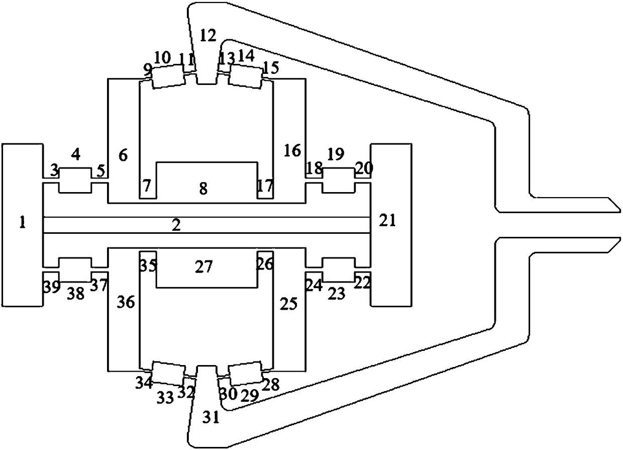
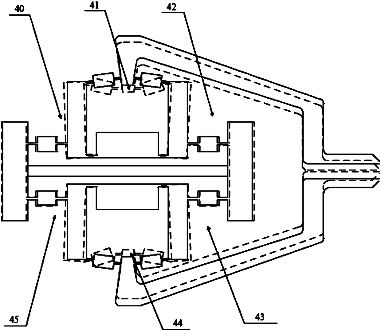
[0024] A microgripper with a two-stage magnification mechanism, such as figure 1 , 2 As shown, it includes a fixed frame (composed of a fixed frame 8 and a fixed frame 27), displacement input platforms 1, 21, a motion input mechanism 2 (a piezoelectric ceramic driver is used in this embodiment), four groups of first-stage lever mechanisms (primary lever mechanism 40,42,43,45) and two groups of bridge type amplification mechanisms (bridge type amplification mechanism 41 and bridge type amplification mechanism 44), four groups of first stage lever mechanisms and two groups of bridge type amplification mechanisms respectively Symmetrical, and the fulcrum of the first-level lever mechanism is connected to the fixed frame 8, 27 in transmission, the two ends of the motion input mechanism 2 are respectively connected to the displacement input platform 1 and the displacement input platform 21, and the input ends of the four sets of first-level lever mechanisms are respectively The fi...


PUM


Abstract

The invention relates to a microgripper with two stages of magnification mechanisms. The microgripper comprises a motion input mechanism, two displacement input platforms, two fixed racks, four sets of first-stage lever mechanisms, two sets of second-stage bridge type magnification mechanisms and a pair of clamping arms. The displacement platforms are in bilateral symmetry, and the first-stage lever mechanisms are bilaterally symmetric and vertically symmetric. The second-stage bridge type magnification mechanisms are vertically symmetric, and the clamping arms are vertically symmetric. The two ends of the motion input mechanism are connected with the displacement input platforms correspondingly, and the output ends of the displacement input platforms are in transmission connection with the input ends of the second-stage bridge type magnification mechanisms correspondingly through the first-stage lever mechanisms. The output ends of the second-stage bridge type magnification mechanismsare connected with the clamping arms. According to the microgripper, the bridge type magnification mechanisms have symmetry, parallel clamping of a microgripper head is guaranteed, output displacement is directly transferred to the clamping arms, and the microgripper head cannot generate parasitic displacement. The two stages of magnification mechanisms are adopted, displacement subjected to first-stage magnification is input into the bridge type magnification mechanisms, and a larger magnification ratio is achieved.

Description

technical field [0001] The invention relates to a clamping device, in particular to a micro clamp with a two-stage enlargement mechanism. Background technique [0002] As the execution terminal of the micro-operating system, the micro-clamp has been widely used in many fields such as micro-electro-mechanical systems, scanning probe microscopes, ultra-precision machining, optical adjustment, and biological cell manipulation. The micro gripper generally includes a driving mechanism and a motion transmission mechanism. The motion transmission mechanism usually includes a lever mechanism, a double rocker mechanism and a bridge mechanism. Generate parasitic displacement, while the bridge mechanism can avoid the generation of parasitic displacement. [0003] Chinese patent CN 103331748A discloses a miniaturized flexible micro-clamp driven by piezoelectric ceramics, which includes a base, a pre-tightening screw, a motion transmission mechanism, a first fixing screw, a second fixin...

Claims


Application Information

Patent Timeline
Patent Type & Authority Applications(China)
IPC IPC(8): B25J7/00B25J9/10
CPCB25J7/00B25J9/106
Inventor 丁严梅峻华赖磊捷
Owner SHANGHAI UNIV OF ENG SCI
Why Eureka
Try Eureka