Pipe cleaning equipment for tunnel construction

A technology for cleaning equipment and tunnel construction, which is applied in the direction of cleaning hollow objects, cleaning methods and utensils, chemical instruments and methods, etc., and can solve the problems of poor cleaning effect and high manufacturing cost

Inactive Publication Date: 2018-05-29
刘占明
View PDF5 Cites 24 Cited by
  • Summary
  • Abstract
  • Description
  • Claims
  • Application Information

AI Technical Summary

Problems solved by technology

[0005] In order to overcome the shortcomings of high manufacturing cost and poor cleaning effect of existing pipe cleaning equipment, the technical problem

Method used


Image

  • Pipe cleaning equipment for tunnel construction
  • Pipe cleaning equipment for tunnel construction
  • Pipe cleaning equipment for tunnel construction

Examples


Embodiment 1

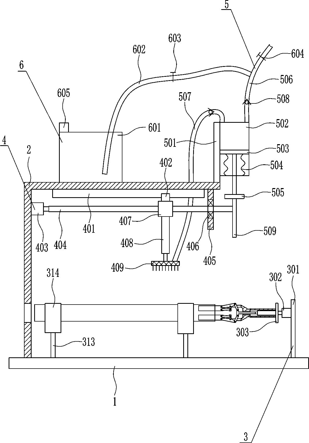
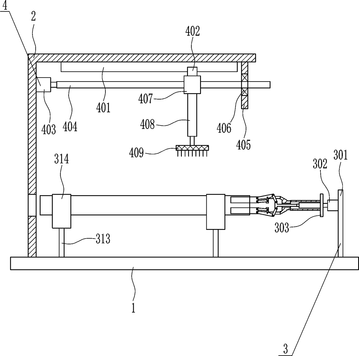
[0032] A pipe cleaning equipment for tunnel construction, such as Figure 1-6 As shown, it includes a bottom plate 1, a 7-type plate 2, a rotating device 3 and a scrubbing device 4. The left side of the top of the bottom plate 1 is connected with a 7-type plate 2, and the top of the 7-type plate 2 is equipped with a scrubbing device 4, and the top of the bottom plate 1 is installed with a The rotating device 3 and the brushing device 4 are located directly above the rotating device 3 .

Embodiment 2

[0034] A pipe cleaning equipment for tunnel construction, such as Figure 1-6 As shown, it includes a bottom plate 1, a 7-type plate 2, a rotating device 3 and a scrubbing device 4. The left side of the top of the bottom plate 1 is connected with a 7-type plate 2, and the top of the 7-type plate 2 is equipped with a scrubbing device 4, and the top of the bottom plate 1 is installed with a The rotating device 3 and the brushing device 4 are located directly above the rotating device 3 .

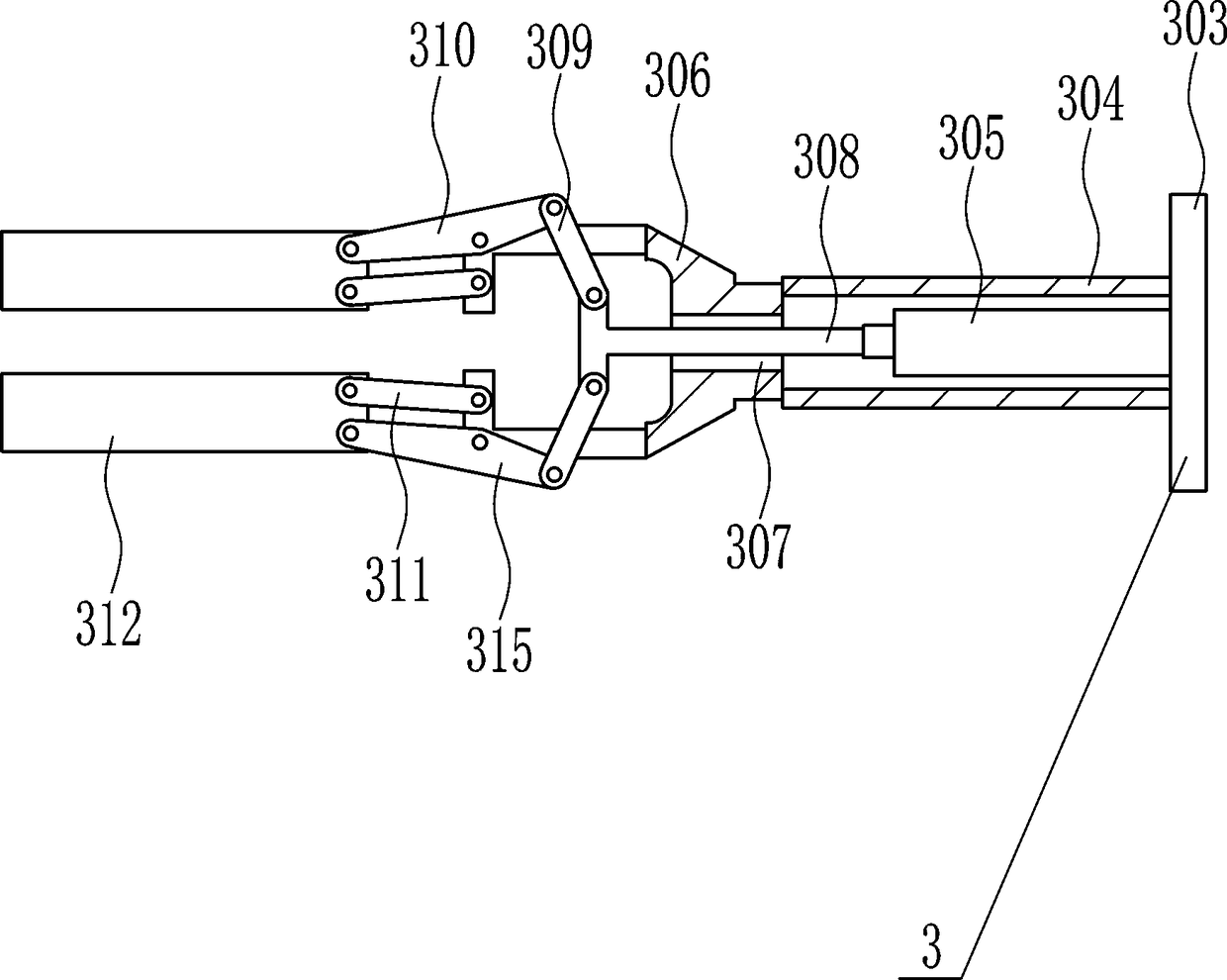
[0035] The rotating device 3 includes a first mounting plate 301, a first motor 302, a connecting plate 303, a hollow pipe 304, a first cylinder 305, an n-type bar 306, a T-shaped connecting rod 308, a first connecting rod 309, and a second connecting rod 310, the third connecting rod 311, the fixed rod 312, the support rod 313, the u-shaped block 314 and the fourth connecting rod 315, the top of the bottom plate 1 is symmetrically connected with the support rod 313, and the tops of the two su...

Embodiment 3

[0037] A pipe cleaning equipment for tunnel construction, such as Figure 1-6 As shown, it includes a bottom plate 1, a 7-type plate 2, a rotating device 3 and a scrubbing device 4. The left side of the top of the bottom plate 1 is connected with a 7-type plate 2, and the top of the 7-type plate 2 is equipped with a scrubbing device 4, and the top of the bottom plate 1 is installed with a The rotating device 3 and the brushing device 4 are located directly above the rotating device 3 .

[0038] The rotating device 3 includes a first mounting plate 301, a first motor 302, a connecting plate 303, a hollow pipe 304, a first cylinder 305, an n-type bar 306, a T-shaped connecting rod 308, a first connecting rod 309, and a second connecting rod 310, the third connecting rod 311, the fixed rod 312, the support rod 313, the u-shaped block 314 and the fourth connecting rod 315, the top of the bottom plate 1 is symmetrically connected with the support rod 313, and the tops of the two su...


PUM


Abstract

The invention relates to cleaning equipment, in particular relates to the pipe cleaning equipment for tunnel construction. The pipe cleaning equipment for tunnel construction is low in manufacturing cost and good in cleaning effect. The pipe cleaning equipment for tunnel construction comprises a bottom plate; the left side of the top of the bottom plate is connected with a 7-shaped plate, and theinner top of the 7-shaped plate is provided with a scrubbing device; and the top of the bottom plate is provided with a rotary device, and the scrubbing device is located right above the rotary device. Through the rotary device, the pipe can be fixed, and the pipe can be driven to rotate; and through the scrubbing device, the pipe can be brushed, and through the scrubbing device, a water sprayingdevice can also be driven to work, so that the pipe can be cleaned more completely.

Description

technical field [0001] The invention relates to a cleaning device, in particular to a pipe cleaning device for tunnel construction. Background technique [0002] A tunnel is an engineering building buried in the ground, and it is a form of human use of underground space. Tunnels can be divided into traffic tunnels, hydraulic tunnels, municipal tunnels, and mine tunnels. [0003] The existing pipe cleaning equipment has the disadvantages of high manufacturing cost and poor cleaning effect, so it is urgent to develop a pipe cleaning equipment for tunnel construction with low manufacturing cost and good cleaning effect. Contents of the invention [0004] (1) Technical problems to be solved [0005] In order to overcome the shortcomings of high manufacturing cost and poor cleaning effect of existing pipe cleaning equipment, the technical problem to be solved by the present invention is to provide a pipe cleaning equipment for tunnel construction with low manufacturing cost a...

Claims


Application Information

Patent Timeline
IPC IPC(8): B08B9/023
CPCB08B9/023
Inventor 曹晓娟李慧琴刘林鑫
Owner 刘占明
Why Eureka
Try Eureka