
A stern energy-saving device applied to water-jet propulsion high-speed ships

A water-jet propulsion and energy-saving device technology, which is applied in the direction of hull, ship construction, hull design, etc., can solve the problems of horizontal and vertical instability, limited drag reduction effect, non-adjustable angle, etc., and achieve the effect of improving comprehensive economic performance

Active Publication Date: 2019-06-28
708TH RES INST OF CSSC
View PDF6 Cites 0 Cited by
  • Summary
  • Abstract
  • Description
  • Claims
  • Application Information

AI Technical Summary

Problems solved by technology

If the wave suppressor is used, in order to avoid interfering with the reversing water flow of the reversing bucket, it can only be installed within a limited width, and the drag reduction effect is limited; if a wedge-shaped plate is used, although it can be arranged within the full width of the stern, because the angle is fixed and cannot be adjusted, It is impossible to obtain the best drag reduction effect at different speeds, and it also leads to increased resistance at low speeds and when reversing; if a cutoff plate is used, although it can also be arranged within the full width of the stern, it can also be vertically movable within the full width. Adjustment, but when the height of the stretch is not right, it is prone to lateral and longitudinal instability during navigation

Method used


Image

  • A stern energy-saving device applied to water-jet propulsion high-speed ships
  • A stern energy-saving device applied to water-jet propulsion high-speed ships
  • A stern energy-saving device applied to water-jet propulsion high-speed ships

Examples


Embodiment approach

[0034] Figure 4 It is the front view of the junction of the cutoff plate and the wave suppression plate of the stern energy-saving device applied to the water jet propulsion high-speed ship of the present invention, Figure 5 It is a top view of the junction of the cutoff plate and the wave suppression plate of the stern energy-saving device applied to the water-jet propelled high-speed ship of the present invention.

[0035] In further embodiments of the present invention, see Figure 4 and Figure 5 As shown, the positioning plate 7 is provided with a slot 15 at one end close to the cut-off plate 4, and one end of the cut-off plate 4 is arranged in the slot 15, so that the cut-off plate 4 can only slide vertically and cannot slide horizontally.

[0036] In further embodiments of the present invention, please continue to refer to image 3 shown in the image 3 The other ends of the two wave-pressing plates 6 at the middle left end and the right-hand end are respectively ...


PUM


Abstract

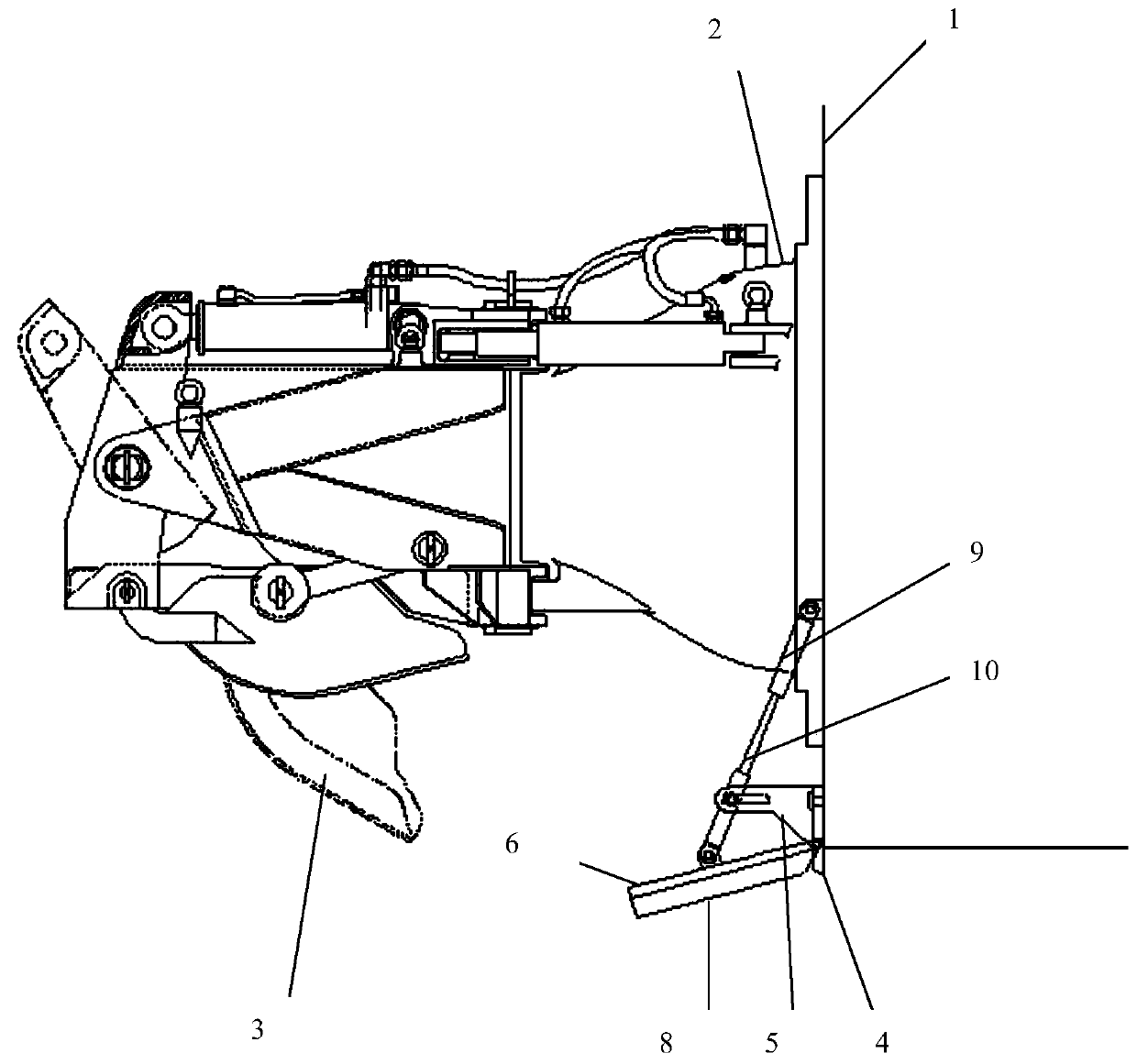
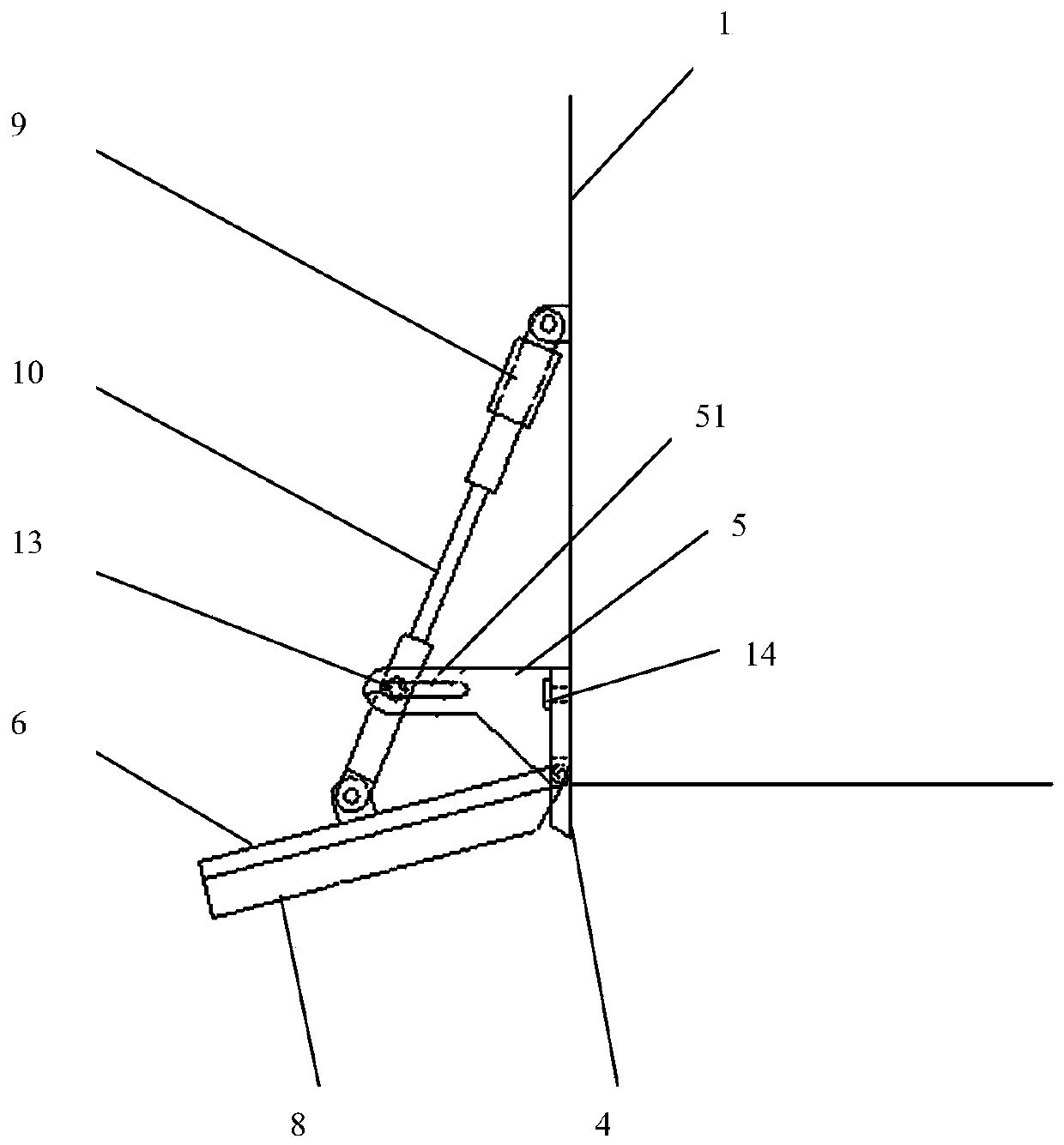
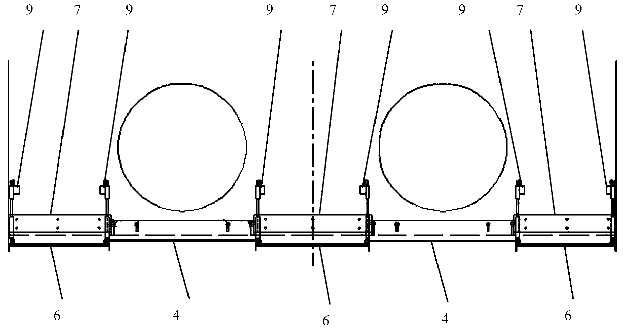
The invention provides a stern energy-saving device applied to a water-spraying propelling high-speed ship. The stern energy-saving device comprises a plurality of intercepter plates which are arranged on the side, close to a nozzle of a water-spraying propeller, of the lower end of a stern transom plate. Lifting lugs are fixed to the two sides of the other side face, opposite to the stern transomplate, on each intercepter plate correspondingly, and a horizontal sliding groove is formed in each lifting lug. The two sides of each intercepter plate are each provided with a positioning plate, and a wave suppression plate is arranged on each positioning plate. Side edge end plates are fixed to the two sides of each wave suppression plate correspondingly, and an output part of each driving device is connected with one end of a wave suppression plate supporting rod. The other end of each wave suppression plate supporting rod is hinged to the middle of the corresponding wave suppression plate. A plurality of first positioning pins are arranged in the multiple horizontal sliding grooves, and one end of each first positioning pin is fixedly connected with the corresponding wave suppressionplate supporting rod. According to the different navigational speed working conditions of the high-speed ship, downward-pressing angles of the stern wave suppression plates and downward-stretching depths of the intercepter plates are simultaneously adjusted, the optimal resistance performance can be achieved at each navigational speed, and the optimal comprehensive resistance-reducing effect is achieved.

Description

technical field [0001] The invention relates to the technical field of ship hydrodynamic energy-saving device design, in particular to a stern energy-saving device. Background technique [0002] The stern breaker, stern wedge and cut-off plate are three energy-saving devices commonly used on high-speed boats. All of them have the effect of adjusting the trim angle and reducing the resistance of the ship at high speed. Among them, the breaker is equivalent to increasing the length of the bottom of the ship. , it can also increase the longitudinal stability of the ship when sailing at high speed and avoid the effect of "dolphin movement". In order to obtain the maximum drag reduction effect, conventional high-speed ships usually install full-width wave breakers, wedge plates or interceptors at the tail, and usually only one of them is used. For high-speed ships using water jet propulsion, water jet nozzles and reversing buckets are arranged outside the stern seal. If the wav...

Claims


Application Information

Patent Timeline
Patent Type & Authority Patents(China)
IPC IPC(8): B63B1/32
CPCB63B1/32Y02T70/10
Inventor 熊小青陈红梅韦红刚于海冯毅
Owner 708TH RES INST OF CSSC
Learn More