
Computer-based quality management testing device

A detection device and quality management technology, which is applied in the direction of measuring devices, optical devices, instruments, etc., can solve the problems of inconvenient measurement, insufficient accuracy of detection data, and insufficient enthusiasm, so as to increase the density of strict inspection, novel design structure, The effect of preventing flooding

Inactive Publication Date: 2018-05-29
成都朋远亦乐科技有限公司
View PDF0 Cites 5 Cited by
  • Summary
  • Abstract
  • Description
  • Claims
  • Application Information

AI Technical Summary

Problems solved by technology

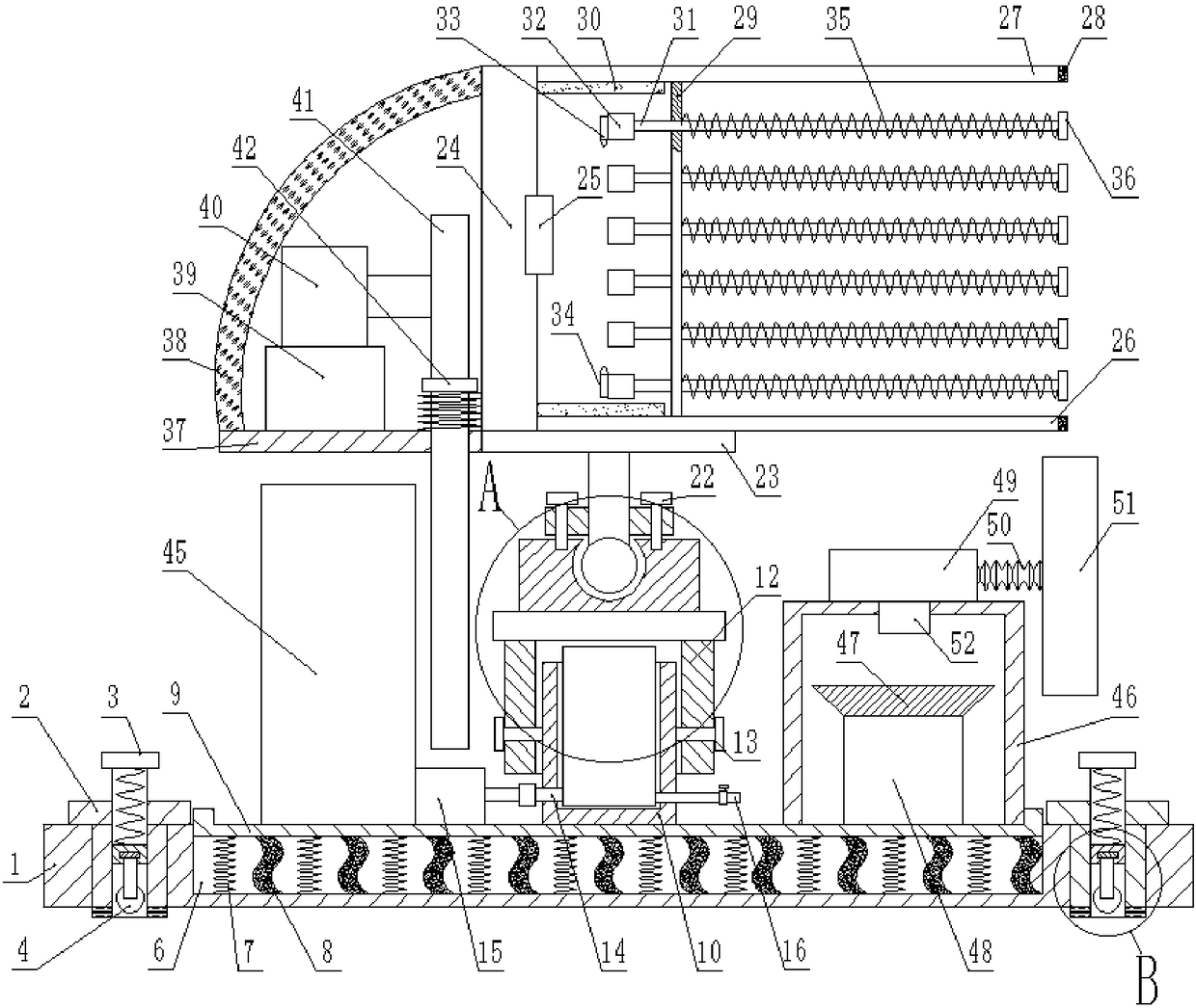
[0002] Quality management testing refers to the overall combination of measuring instruments and auxiliary equipment for measurement needs. Some auxiliary equipment or tools for measurement are often included in the list of commonly used measuring tools. It is very important to test buildings in construction. To ensure the safety of building use in the later stage, the existing quality management inspection can simply measure the height of the building. At the same time, the measurement of this kind of building is usually completed by two people, which brings some inconvenience to the measurement. When measuring the building , the flatness detection of the wall is also more important, which can ensure the use of later buildings, and there are many deficiencies in the current stage of construction quality detection devices, for example, the detection system is not perfect enough, the enthusiasm is not enough, and the accuracy of detection data is not enough , and there are few testing items, it is impossible to fully analyze the problems of the construction quality testing device

Method used


Image

  • Computer-based quality management testing device
  • Computer-based quality management testing device
  • Computer-based quality management testing device

Examples


Embodiment Construction

[0020] The present invention will be described in further detail below in conjunction with the accompanying drawings and specific embodiments:

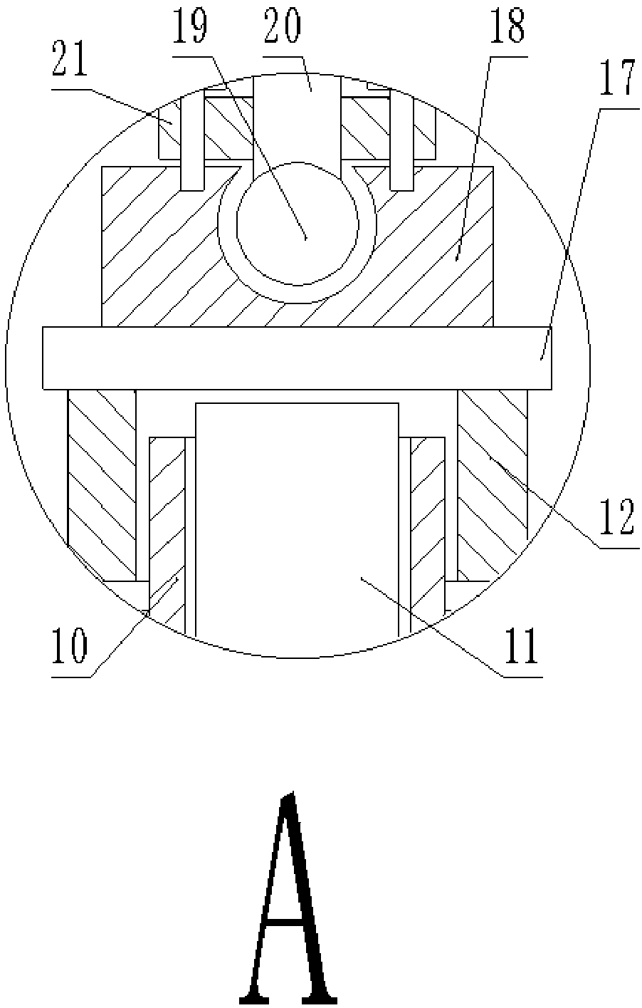
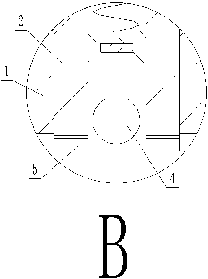
[0021] like figure 1 , figure 2 , image 3 , Figure 4 As shown, a computer-based quality management testing device includes a base 1, and two T-shaped sleeves 2 are embedded and fixed on the edge sides of both sides of the base 1, and a screw 3 is screwed into the T-shaped sleeve 2. , the bottom end of the screw 3 is fixedly connected with the universal wheel 4 through the connecting block, the bottom end of the T-shaped sleeve 2 is fixedly attached with a non-slip rubber pad 5, and the center of the base 1 is fixedly provided with a groove 6, so A plurality of shock-absorbing springs 7 and rubber hoses 8 are fixed in the groove 6, and a rubber hose 8 is arranged between every two shock-absorbing springs 7, and the tops of the shock-absorbing springs 7 and the rubber hose 8 are fixed. A U-shaped bottom plate 9 is provided, the s...


PUM

PropertyMeasurementUnit
The inside diameter ofaaaaaaaaaa

Abstract

The invention discloses a computer-based quality management testing device. The device comprises a base, two T-shaped sleeve tubes are fixedly embedded in two edge sides of two sides of the base, screw rods are in threaded connection with the insides of the T-shaped sleeve tubes, the bottoms of the screw rods are fixedly connected with universal wheels through connecting blocks, anti-skid rubber pads are fixedly attached to the bottoms of the T-shaped sleeve tubes, a groove is formed in the center of the base, a plurality of shock-absorbing springs and rubber hoses are fixedly arranged in thegroove, one rubber hose is arranged between every two shock-absorbing springs, and U-shaped bottom plates are fixedly arranged on the tops of the shock-absorbing springs and the rubber hoses. According to the device, flatness of a wall body of a building can be directly reflected through a flatness measuring device, and the flatness is directly fed back to a computer through a light source signalreceiver, so that the flatness of a measured zone is determined through computing analysis of the computer, a camera passes by the measured zone so that the measured zone can be observed by the camera, and measuring tools can be controlled to change the position and the angle through air bags and universal rotary balls.

Description

technical field [0001] The invention relates to the field of quality management detection, in particular to a computer-based quality management detection device. Background technique [0002] Quality management testing refers to the totality of measuring instruments and auxiliary equipment combined for measurement needs. Some auxiliary equipment or tools used for measurement are often classified as commonly used measuring tools. It is very important to test buildings in buildings. To ensure the safety of the later use of the building, the existing quality management test can simply measure the height of the building. At the same time, the measurement of this kind of building is mostly completed by two people, which brings certain inconvenience to the measurement. When measuring the building , the leveling detection of the wall is also more important, which can ensure the use of the later construction, and the current construction quality detection device has many shortcoming...

Claims


Application Information

Patent Timeline
IPC IPC(8): G01B11/30G01N15/06G01N15/00
CPCG01B11/30G01N15/00G01N15/06
Inventor 王超
Owner 成都朋远亦乐科技有限公司
Learn More