Stable new energy automobile device

A new energy vehicle, stable technology, applied in the direction of coupling devices, electric vehicles, efficient vehicle charging, etc., can solve the problems of reduced service life of new energy vehicles, power failure of new energy vehicles, destruction of new energy vehicles, etc., to reduce electric shock Accidents, safe and stable power supply, and the effect of avoiding electric shock accidents

Inactive Publication Date: 2018-06-01
广州快舟智能环保科技有限公司
View PDF5 Cites 0 Cited by
  • Summary
  • Abstract
  • Description
  • Claims
  • Application Information

AI Technical Summary

Problems solved by technology

[0002] At present, the charging of new energy vehicles needs to be charged after the charging gun is inserted into the charging pile body to be powered on. The connection method is very convenient to operate, but the length of the cable between the charging gun and the new energy vehicle is different. When charging, the cable is often placed randomly. If someone accidentally kicks and hits the cable by mistake, it will cause The charging gun is directly disconnected from the matching connection with the power supply hole of the charging pile body, which will cause a sudden power failure of the new energy vehicle, so that the service life of the new energy vehicle will be reduced, and in serious cases, it will directly cause the destruction of the new energy vehicle. Some plugging methods between charging guns and power supply tanks have potential safety hazards of unstable power supply connections, and existing charging guns are prone to electric shock accidents during plugging and unplugging

Method used


Image

  • Stable new energy automobile device
  • Stable new energy automobile device
  • Stable new energy automobile device

Examples


Embodiment Construction

[0022] The preferred embodiments of the present invention will be described in detail below in conjunction with the accompanying drawings, so that the advantages and features of the present invention can be more easily understood by those skilled in the art, so as to define the protection scope of the present invention more clearly.

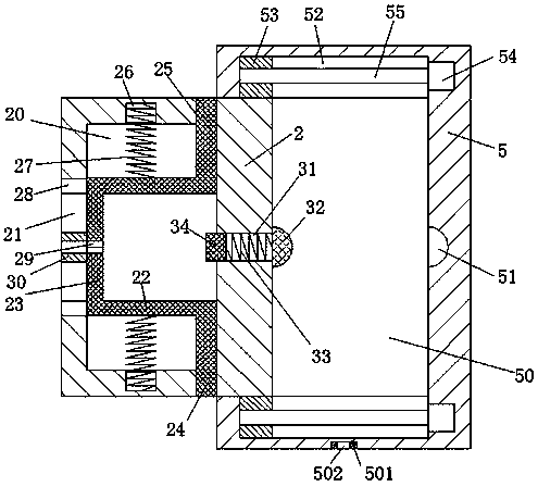
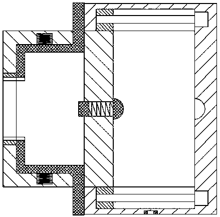
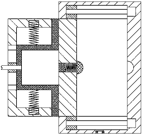
[0023] refer to Figure 1-7 The shown stable new energy vehicle device includes a charging pile body 5 and a charging gun 1 connected to the new energy vehicle through a cable 11, and a mounting plate 501 is fixedly installed at the lower part of the front and rear end faces of the charging pile body 5, The mounting plate 501 is provided with a fixing hole 502 connecting up and down, and the fixing hole 502 is used to pass a screw, so as to fix the charging pile body 5 firmly. The charging pile body 5 is provided with a notch to The left sliding groove 50 is provided with a sliding plate 2 that can slide left and right, and the middle end of the ...


PUM


Abstract

The invention discloses a stable new energy automobile device, comprising a charging pile body and a charging gun connected with a new energy automobile via a cable. Mounting plates are fixedly mounted on the lower portions of the front end surface and the rear end surface of the charging pile body, and vertically-penetrating mounting holes are formed in the mounting plates. A slipping groove witha leftward groove opening is formed in the charging pile body, a slipping plate is arranged in the slipping groove in a left-right slipping mode, and an electric connecting port is formed in the middle end of the right end wall of the slipping groove. First slipping cavities are mutually symmetrically formed in the front end wall and the rear end wall of the slipping groove, and flanges connectedwith the first slipping cavities in a slipping fit mode are mutually and symmetrically arranged on the right sides of the front end surface and the rear end surface of the slipping plate. According to the stable new energy automobile device, the overall structure is simple, the production cost is low, power supplying is safe and stable, electric shock accidents in the present life are effectivelyreduced, the occurrence of power failure accidents of the new energy automobile due to accidental kicking and collision can be avoided, locking of the charging gun is safe and reliable, and the wholedevice is easy and convenient to operate.

Description

technical field [0001] The invention relates to the field of new energy vehicles, in particular to a stable new energy vehicle device. Background technique [0002] At present, the charging of new energy vehicles needs to be charged after the charging gun is inserted into the charging pile body to be powered on. The connection method is very convenient to operate, but the length of the cable between the charging gun and the new energy vehicle is different. When charging, the cable is often placed randomly. If someone accidentally kicks and hits the cable by mistake, it will cause The charging gun is directly disconnected from the matching connection with the power supply hole of the charging pile body, which will cause a sudden power failure of the new energy vehicle, so that the service life of the new energy vehicle will be reduced, and in serious cases, it will directly cause the destruction of the new energy vehicle. Some plugging methods between charging guns and power...

Claims


Application Information

Patent Timeline
Patent Type & Authority Applications(China)
IPC IPC(8): H01R13/639H01R13/70B60L11/18
CPCB60L53/16B60L53/31H01R13/639H01R13/701H01R2201/26Y02T10/70Y02T10/7072Y02T10/92Y02T90/12Y02T90/14
Inventor 张明
Owner 广州快舟智能环保科技有限公司
Why Eureka
Try Eureka