Dust remover device with high safety

A dust collector and safety technology, which is used in vacuum cleaners, transportation and packaging, cleaning equipment, etc., can solve the problems of increased damage probability, inconvenience, and movement of dust collectors, and achieves stable operation, convenient use and simple structure.

Inactive Publication Date: 2018-06-05
永春豪田工艺品有限公司
View PDF6 Cites 0 Cited by
  • Summary
  • Abstract
  • Description
  • Claims
  • Application Information

AI Technical Summary

Problems solved by technology

[0002] The dust collectors used in some industrial plants are generally large and heavy. In order to facilitate the movement, rollers are often set at the bottom of the dust collector to improve the moving performance. The rollers of traditional industrial dust collectors are generally universal wheels, so It is very inconvenient to set up the brake device. When the dust collector is in a static state, if it is touched by humans, it may cause the movement of the dust collector in an unsafe state. In severe cases, it will cause collisions, which will increase the probability of damage. In some slopes The section of the road is also prone to slippery slopes, so this kind of dust collector has a lot of disadvantages and needs to be improved

Method used


Image

  • Dust remover device with high safety
  • Dust remover device with high safety
  • Dust remover device with high safety

Examples


Embodiment Construction

[0024] All features disclosed in this specification, or steps in all methods or processes disclosed, may be combined in any manner, except for mutually exclusive features and / or steps.

[0025] Any feature disclosed in this specification (including any appended claims, abstract and drawings), unless expressly stated otherwise, may be replaced by alternative features which are equivalent or serve a similar purpose. That is, unless expressly stated otherwise, each feature is one example only of a series of equivalent or similar features.

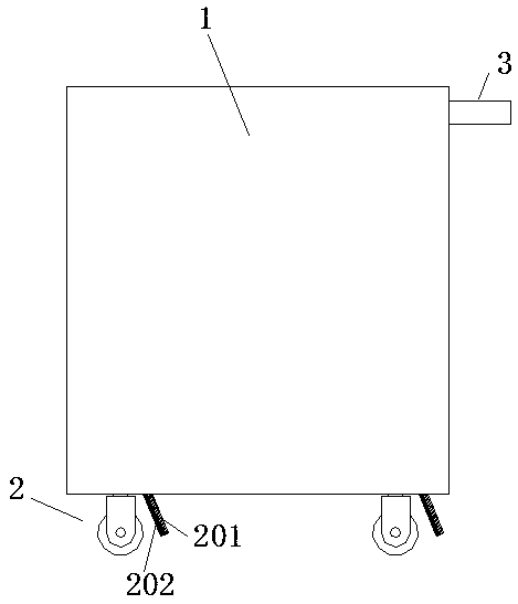
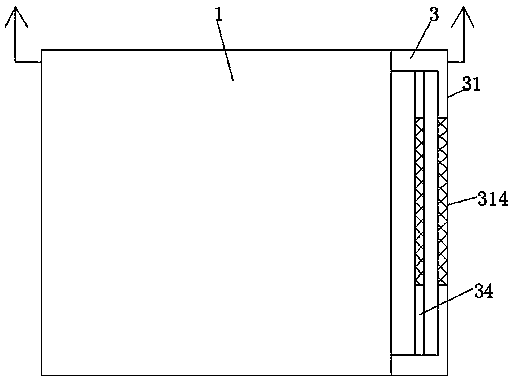
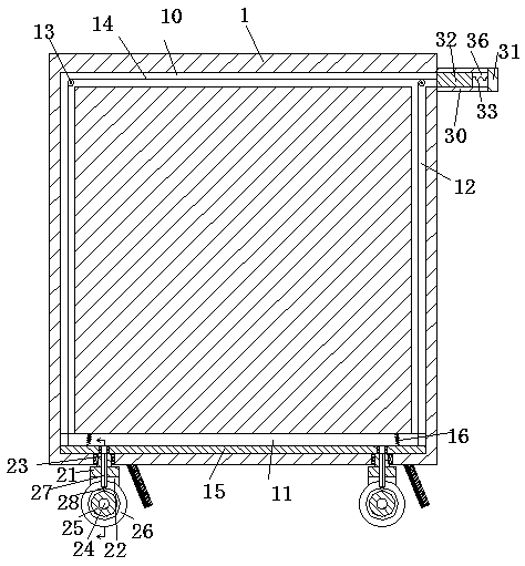
[0026] Such as Figure 1-6 As shown, a high-safety dust collector device of the present invention includes a dust collector 1, a sliding device 2 is installed at the bottom of the dust collector 1, and a push frame part 3 is fixedly installed on the upper right end surface of the dust collector 1;

[0027] The sliding device 2 includes a rotary sleeve 23 rotatably installed in the bottom wall of the dust collector 1, the lower end of the rota...


PUM


Abstract

Provided is a dust remover device with high safety. The dust remover device comprises a dust remover, the bottom of the dust remover is provided with a sliding device, the upper end of the right end face of the dust remover is fixedly provided with a push frame part; the sliding device comprises a rotating sleeve rotationally arranged in the bottom wall of the dust remover, the lower end of the rotating sleeve is fixedly provided with an assembly plate, both of the front end and rear end of the assembly plate are fixedly provided with protrusive plates extending downwards, a rotating shaft isrotationally arranged between the two protrusive plates, the rotating shaft is fixedly provided with a toothed wheel, the front and rear end faces of the toothed wheel are fixedly provided with a rotating wheel; the push frame part comprises push frame arms which are fixedly arranged at the upper end of the right end face of the dust remover and the front and rear push frame arms mutually symmetric, a connecting rod is arranged between the two push frame arms, the inner side end face of each push frame arm is provided with sliding grooves extending to the left and the right, sliding blocks areuniformly slidingly arranged in each sliding groove, and a tension rod is fixedly arranged between each two sliding blocks.

Description

technical field [0001] The invention relates to the technical field of dust collectors, in particular to a dust collector device with high safety. Background technique [0002] The dust collectors used in some industrial plants are generally large and heavy. In order to facilitate the movement, rollers are often set at the bottom of the dust collector to improve the moving performance. The rollers of traditional industrial dust collectors are generally universal wheels, so It is very inconvenient to set up the brake device. When the dust collector is in a static state, if it is touched by humans, it may cause the movement of the dust collector in an unsafe state. In severe cases, it will cause collisions, which will increase the probability of damage. In some slopes The road section is also prone to slippery slopes, so this kind of dust collector has a lot of disadvantages and needs to be improved. Contents of the invention [0003] The object of the present invention is ...

Claims


Application Information

Patent Timeline
IPC IPC(8): A47L9/00B60B33/00
CPCA47L9/009B60B33/0078
Inventor 林培双张迪超
Owner 永春豪田工艺品有限公司
Why Eureka
Try Eureka