Torque-transmitting electrical connectors for adaptive rotational position
A technology of rotating position and transmitting torque, which is applied in the direction of connection, two-part connecting device, circuit, etc., can solve the problems of inability to realize axial displacement and torque transmission, etc., and achieve easy mass promotion, stable and reliable torque transmission, and load protection The effect of parts
- Summary
- Abstract
- Description
- Claims
- Application Information
AI Technical Summary
Problems solved by technology
Method used
Image
Examples
Embodiment Construction
[0020] Now in conjunction with embodiment, accompanying drawing, the present invention will be further described:
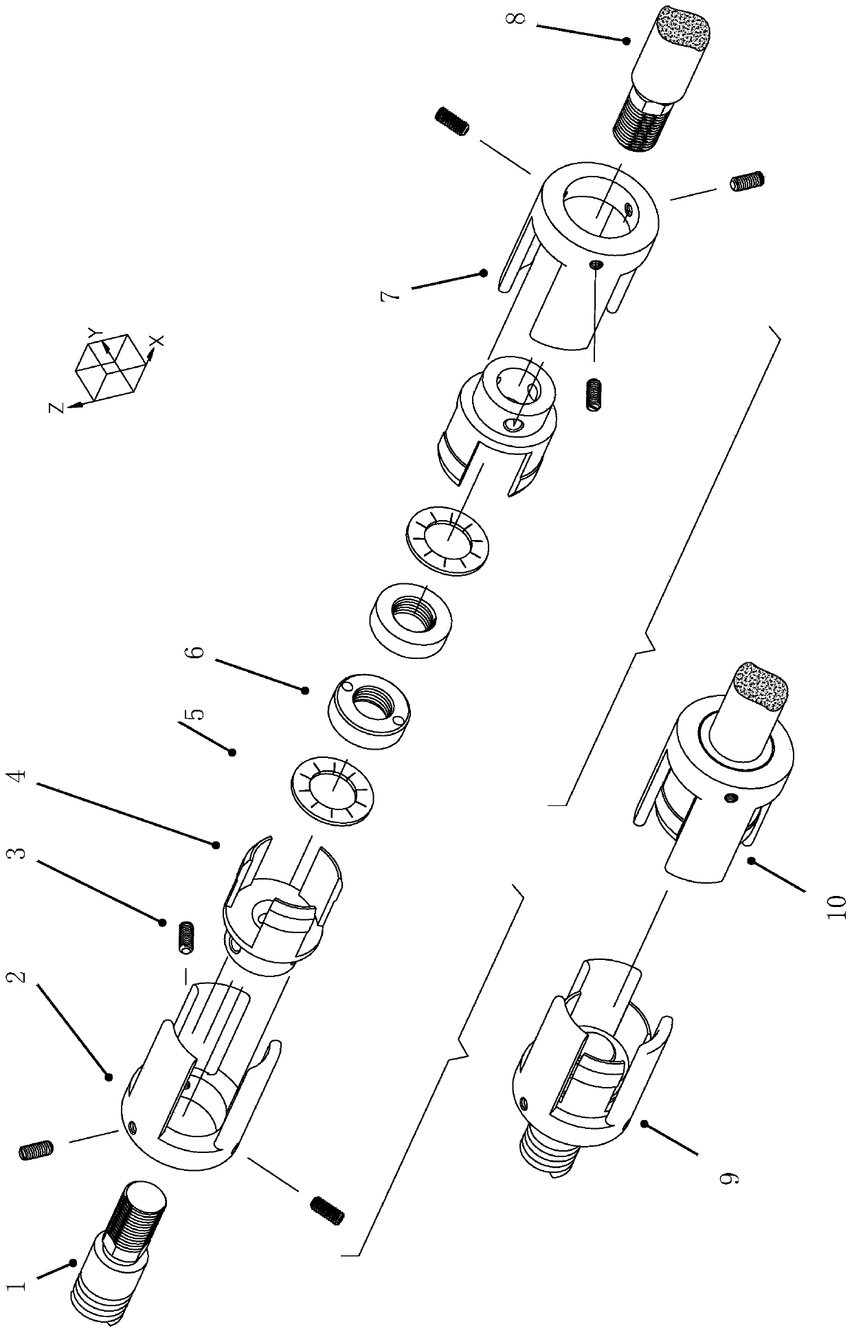
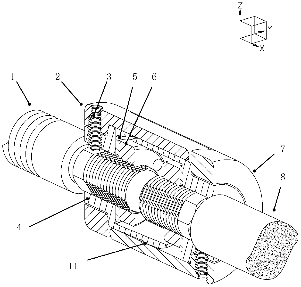
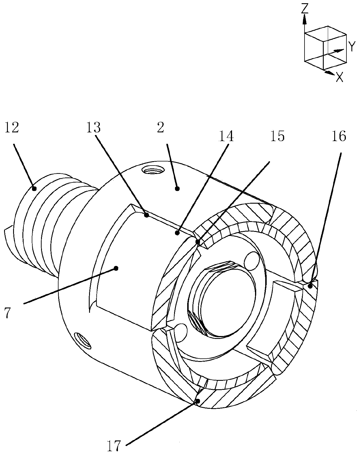
[0021] An electrical connector for torque transmission with adaptive rotational position, including an input element 9 and an output element 10, an array of elastic pins and socket elements at intervals of 120° in the circumferential direction of the element, forming six radial elastic pin-hole engagement structures, At the same time, the cylindrical surface of the side wall of the socket mirror part and the plane of the side wall of the socket part form one-way three motion pairs, and the cylindrical surface of the side wall of the socket part and the side wall plane of the mirror part of the socket form three motion pairs in the opposite direction. A total of 6 motion pairs in both directions to reverse the load. In addition, a threaded segment is provided at one end of the output shaft to achieve an axial displacement that can be accurately measured.
[0022]...
PUM
 Abstract
Description
Claims
Application Information
 - R&D
- Intellectual Property
- Life Sciences
- Materials
- Tech Scout
- Unparalleled Data Quality
- Higher Quality Content
- 60% Fewer Hallucinations
Browse by: Latest US Patents, China's latest patents, Technical Efficacy Thesaurus, Application Domain, Technology Topic, Popular Technical Reports.
© 2025 PatSnap. All rights reserved.Legal|Privacy policy|Modern Slavery Act Transparency Statement|Sitemap|About US| Contact US: help@patsnap.com


