Filter housing with locking cord member

A technology of ropes and components, applied in the field of filter components, can solve the problem of not providing any

Active Publication Date: 2018-06-08
CATERPILLAR INC
View PDF6 Cites 0 Cited by
  • Summary
  • Abstract
  • Description
  • Claims
  • Application Information

AI Technical Summary

Problems solved by technology

The '738 patent provides no remedy for these deficiencies of conventional compression straps

Method used


Image

  • Filter housing with locking cord member
  • Filter housing with locking cord member
  • Filter housing with locking cord member

Examples


Embodiment Construction

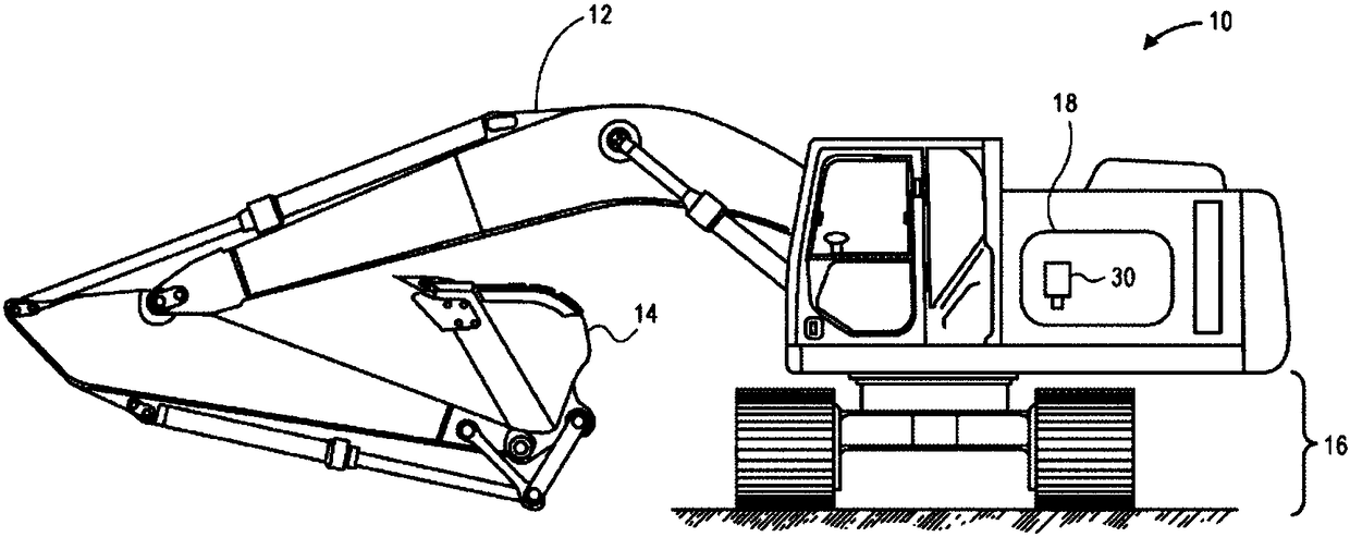
[0031] The present invention relates to a filter assembly. figure 1 Machine 10 is illustrated having various systems and components that are suitable for use with aspects of the invention and that cooperate to accomplish tasks. Machine 10 may embody a stationary or mobile machine that performs some type of operation associated with an industry such as mining, construction, agriculture, transportation, power generation, or another industry known in the art. For example, machine 10 may be such as a backhoe ( figure 1 shown in ), bulldozer, loader, backhoe, motor grader, dump truck, or another earth-moving machine. Machine 10 may include an implement system 12 configured to move a work tool 14 , a drive system 16 for propelling machine 10 , and a power source 18 .

[0032] In a particular example, power source 18 includes an engine configured to combust a fuel, such as diesel, and the fuel is filtered at filter assembly 30 . As fuel passes through the filter assembly 30 , cont...


PUM


Abstract

A connection (148) includes a first component, a second component, a cord member (40), a detent (52, 54), and a catch assembly (44). The first component has an opening with an inner surface (116) anda first annular groove (114) disposed about the inner surface (116). The second component has a top end (118) configured to fit in the opening. The top end (118) has an outer surface (126) with a second annular groove (124) disposed about the outer surface (126). The first annular groove (114) and the second annular groove (124) are configured to form a channel (142) in response to being disposedin cooperative alignment. The cord member (40) is configured to be removably inserted into the channel (142) to secure the first component to the second component. The detent (52, 54) is disposed on the cord member (40). The catch assembly (44) is configured to engage the detent (52, 54) and provide resistance to movement of the cord member (40) relative to the catch assembly (44).

Description

technical field [0001] This patented invention relates generally to filter assemblies, and more particularly to the connection between the base and the housing of the filter assembly. Background technique [0002] Filter assemblies are known in the art for use in various applications, such as internal combustion engines, hydraulic or pneumatic systems, and the like. These filter assemblies can be used to filter fluids in fuel systems, lube oil systems, hydraulic oil systems, air or exhaust filtration systems, and more. There are different types of filters such as canister filters, spin-on filters, etc. It is very important to service such filter assemblies at regular intervals as the filter elements in these filter assemblies can become clogged with impurities in the fluid being filtered and may need to be replaced. [0003] US Patent No. 6,726,738, entitled "Air Filter Assembly" (hereinafter "the '738 Patent") describes a filter assembly having a snap assembly to connect ...

Claims


Application Information

Patent Timeline
Patent Type & Authority Applications(China)
IPC IPC(8): B01D46/00B01D35/30B01D46/24F16L37/14
CPCB01D35/30B01D46/0004B01D46/0031B01D46/2411F16L37/148B01D2201/291B01D2201/40B01D2265/02B01D2265/027B01D46/0005B01D29/96B01D46/4227F16B2/08F16B2/14
Inventor B·莫里斯S·欧尼斯J·里斯
Owner CATERPILLAR INC
Why Eureka
Try Eureka