Pleated filter media

A technology of filter media and pleats, which is applied in the field of pleated patterns of filter media, and can solve problems such as clogging of pleated filters

Active Publication Date: 2017-02-15
CATERPILLAR INC
View PDF6 Cites 0 Cited by
  • Summary
  • Abstract
  • Description
  • Claims
  • Application Information

AI Technical Summary

Problems solved by technology

Thus, conventional pleated filters can become clogged when assigned to filter particles outside the desired particle size range

Method used


Image

  • Pleated filter media
  • Pleated filter media
  • Pleated filter media

Examples


Embodiment Construction

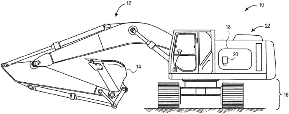
[0024] figure 1 An exemplary machine 10 is shown having various systems and components that cooperate to accomplish tasks. Machine 10 may embody a stationary or mobile machine performing some type of operation associated with industries such as mining, construction, agriculture, transportation, power generation, or other industries known in the art. For example, machine 10 may be an earth moving machine, such as an excavator ( figure 1 shown), bulldozers, loaders, backhoes, motor graders, loading and unloading trucks or other earth moving machines. Machine 10 may include an implement system 12 configured to move a work tool 14 , a drive system 16 for propelling machine 10 , and a power source 18 .

[0025] In a particular example, power source 18 includes an engine configured to combust a fuel, such as diesel, in the presence of air. Air may be filtered through filter cartridge assembly 20 . As air passes through the filter cartridge assembly 20 , contaminants such as dust...


PUM


Abstract

A filter (60) element includes a center tube (64) and a blank (30) of a filter media (32). The center tube (64) has a first end and a second end. The blank (30) is folded into a plurality of triangles (38). Each triangle is disposed adjacent to another of the plurality of triangles (38) to form a series of triangular pleats (40) to form a pleated filter media (32). The pleated filter media (32) is disposed about the center tube (64). A cross sectional area of the pleated filter media (32) proximal to each of the first end and the second end is greater than a cross sectional area of the pleated filter media (32) at a point between the first end and the second end.

Description

technical field [0001] The present invention relates generally to filter media, and more particularly to a pleating pattern and method for making a shaped filter media. Background technique [0002] Filter elements are known for filtering particulates or other contaminants from fluids (eg, air, fuel, coolant, etc.). In general, the large surface area of ​​the filter media in a filter element facilitates efficient filtration of fluids. To provide such a large surface area, filter media is often pleated. Additionally, conventional filter housings tend to be relatively large. To accommodate such filter housings, the filter housings are often located outside the engine compartment of conventional earth-moving equipment. [0003] However, having the filter housing outside the engine compartment is problematic for various reasons, for example, the filter housing must be made stronger, the filter housing may be exposed to a dirtier environment, and the location between the filte...

Claims


Application Information

Patent Timeline
IPC IPC(8): B01D29/21B01D46/52
CPCB01D29/21B01D46/521B01D46/522B01D2201/125B01D2275/206B01D2201/02B01D2275/201
Inventor B·A·莫里斯
Owner CATERPILLAR INC
Why Eureka
Try Eureka