
Medical tube clamp with U-shaped groove

A technology of U-shaped grooves and pipe clamps, which is applied to other medical devices, valves, etc., and can solve the problems of hose failure, failure to install pipe clamps, failure to install, etc.

Active Publication Date: 2018-06-15
鄂东医疗集团市中心医院
View PDF5 Cites 2 Cited by
  • Summary
  • Abstract
  • Description
  • Claims
  • Application Information

AI Technical Summary

Problems solved by technology

However, usually one end of the flexible medical tube is connected to the medical device, and the other end is connected to the human body; the medical tube clip of this structure can only be inserted into the tube through the tube head to install it in advance, and cannot be installed from the medical hose. Install the clamp in any intermediate position, no subsequent installation in the medical hose
If in the process of medical treatment, a pipe clip is to be added to a certain hose, or the pipe clip needs to be replaced immediately if the existing hose fails, the above patent application cannot meet this need

Method used


Image

  • Medical tube clamp with U-shaped groove
  • Medical tube clamp with U-shaped groove
  • Medical tube clamp with U-shaped groove

Examples


Embodiment Construction

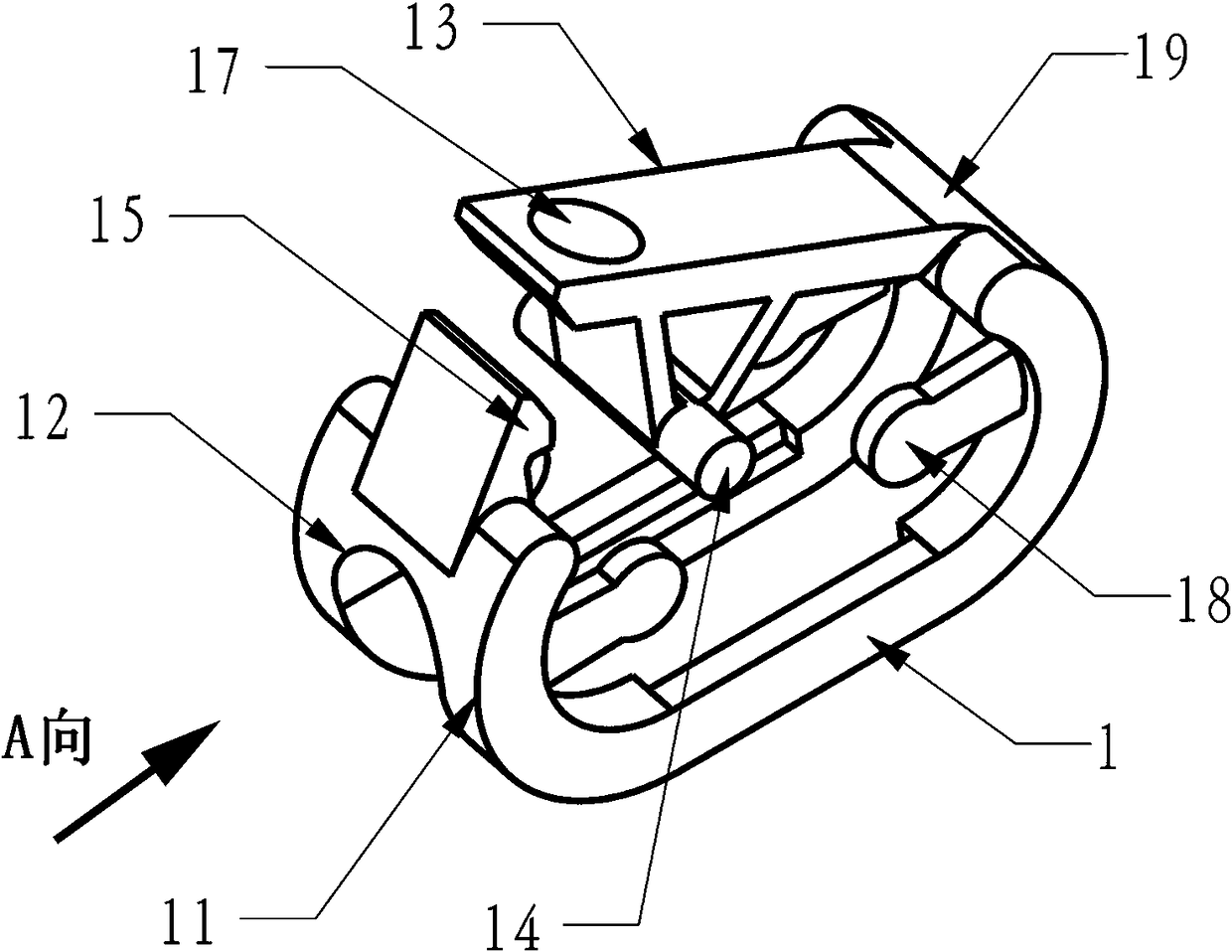
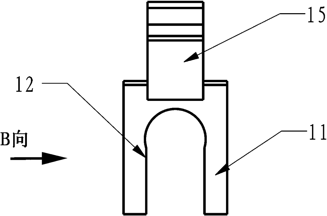
[0014] In the figure, the medical pipe clamp with U-shaped groove has a U-shaped groove 12 on the side of the pipe clamp body 1, and any middle position of the hose 3 can be placed in the U-shaped groove 12; the turning on the left side of the pipe clamp body 1 There is a ratchet 15 at the front end of the place 11; the front end of the turning place 11 on the right side of the pipe clamp body 1 is connected with a hinged plate 13 through a hinge 19; The positioning table 22 is placed in the positioning groove 16; the lower teeth 21 are arranged on the middle part of the lower tooth body 2, and the upper teeth 14 are arranged on the middle part below the hinge plate 13. The function of the positioning groove 16 is to prevent the slippage of the position of the lower tooth body 2 . Pipe clamp body 1 and hinge plate 13 are made into one, and the thickness of the material at hinge 19 is less than the thickness of hinge plate 13, and the deformation of the material at hinge 19 is ...


PUM


Abstract

Disclosed is a medical tube clamp with a U-shaped groove. The medical tube clamp has a U-shaped groove on the side surface of a tube clamp body, and any middle section of the hose is placed in the U-shaped groove; a pawl is arranged at the front of the bend on the left of the tube clamp; The front end of the elbow on the right side of the tube clamp is connected with a hinge plate by a rotary hinge; a positioning groove is arranged on the lower connecting section of the left and right turning, and the positioning table of the lower tooth body is placed in the positioning groove; a lower toothis arranged above the middle part of the lower tooth body, and a upper tooth is arranged at the middle part under the hinge plate. The tube clamp body is integrated with the hinge plate, the materialthickness at the turning hinge point is smaller than the hinge plate; the material deformation is used at the turning hinge point as hinge when press is downward; alternatively, the tube clamp body and the hinge plate are separated structures, and the rotating shaft is added at the hinge. The right and left corners are connected with elastic baffles.

Description

technical field [0001] The invention relates to a pipe clip, especially a "medical pipe clip with a U-shaped groove", which is used in the medical process to control the circulation and cut-off of the medical hose. Background technique [0002] In medical procedures, flexible medical tubing is usually used as a delivery tube to constitute an extracorporeal circulation circuit or an infusion line for auxiliary circulation of body fluids such as blood or drug solutions, and the like. Flexible medical tubing is used with a clamping device molded from resin to allow the medical tubing to be closed in the desired position as required. Current clamping devices are less reliable and there is a risk of not being able to completely disconnect the medical tube. Chinese Patent Application No.: 201280009329.3, "Medical Tube Clamp", on opposite surfaces a first plate portion comprising a compression protrusion for closing a medical tube and a second plate portion are provided on both si...

Claims


Application Information

Patent Timeline
IPC IPC(8): A61M39/28
CPCA61M39/28A61M39/284
Inventor 不公告发明人
Owner 鄂东医疗集团市中心医院
Features
  • Generate Ideas
  • Intellectual Property
  • Life Sciences
  • Materials
  • Tech Scout
  • Unparalleled Data Quality
  • Higher Quality Content
  • 60% Fewer Hallucinations
Learn More