Debris preventing device for float water level gauge

A water level gauge and float technology, which is applied in the field of float water level gauge slag prevention device, can solve the problems of hydropower station safety and flood control, economical and reasonable operation of reservoirs, jamming, large errors in water level measurement accuracy, etc.

Pending Publication Date: 2018-06-15
GUIZHOU WUJIANG HYDROPOWER DEV
0 Cites 1 Cited by

AI-Extracted Technical Summary

Problems solved by technology

However, this water level logging is an open logging well, and the residue and sundries on the slope are easily washed into the logging well by rainwater, covered on the float of the water level gauge or wrapped around the wire rope, causing the balance measurement system of the water level gauge to be des...

Abstract

The invention relates to a debris preventing device, in particular to the debris preventing device for a float water level gauge. The device comprises a filtering mechanism and even number groups of upright limiting assemblies located on the installation base of a water level gauge; the filtering mechanism comprises a filtering framework with openings formed in the top and bottom, a filtering netfixedly arranged on the filtering framework and a floating ball fixedly arranged on the filtering framework; the upright limiting assemblies comprise guiding pipes fixedly arranged on the side face ofthe filtering framework and guiding ropes with one ends arranged on the installation base of the water level gauge and the other ends penetrating through the guiding pipes and fixedly provided with weight balancing blocks; the guiding ropes are perpendicular to the water surface, the weight balancing blocks are located under the water, and pulling force impacting on the weight balancing blocks does not generated by the guiding ropes, and under the action of the buoyancy force of water, the up-and-down vertical movement along the guiding ropes of the filtering framework is constrained; the float of the water level gauge is located in the filtering framework. The device has the advantages of being simple in structure and capable of effectively preventing debris from generating influences onthe float water level gauge.

Application Domain

Level indicators by floats

Technology Topic

EngineeringWater level +2

Image

  • Debris preventing device for float water level gauge
  • Debris preventing device for float water level gauge

Examples

  • Experimental program(1)

Example Embodiment

[0019] The specific embodiments of the present invention will be further described below with reference to the accompanying drawings. It should be noted here that the descriptions of these embodiments are used to help the understanding of the present invention, but do not constitute a limitation of the present invention. In addition, the technical features involved in the various embodiments of the present invention described below can be combined with each other as long as they do not conflict with each other.
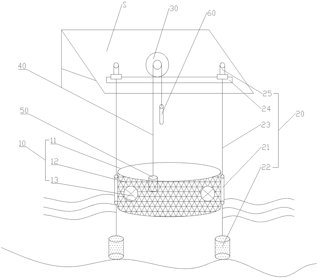
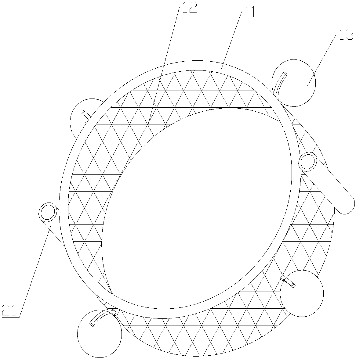
[0020] like figure 1 and figure 2 As shown, the float water level gauge slag prevention device includes a filter mechanism 10 and two sets of vertical limit components 20 arranged on the water level gauge installation base S; the filter mechanism 10 includes a cylindrical filter frame 11, which is fixed on the The filter screen 12 of the filter frame 11, and four float balls 13 fixed on the outside of the filter frame 11 at regular intervals; the vertical limit assembly 20 includes a guide pipe 21 fixed on the side of the filter frame 11, and one end is fixed on the water level gauge The base S is installed, and the other end passes through the guide tube 21 and is fixed with the guide rope 23 of the counterweight 22; the inner diameter of the two guide pipes 21 is 20mm to 30mm, and is opposite to the outside of the filter frame 11; the guide rope 23 and The water surface is vertical, the counterweight block 22 is located at the bottom of the water, and the guide rope 23 does not generate tension on the counterweight block 22. Under the action of water buoyancy, the filter frame 11 is restricted from vertically moving up and down along the guide rope 23.
[0021] The above-mentioned float water level gauge includes a water level runner 30 fixed on the water level gauge installation base S, a water level gauge wire rope 40 wound on the water level runner 30, and a water level gauge float 50 fixed on both ends of the water level gauge wire rope 40 and balance. The hammer 60; the water level gauge float 50 is located in the filter frame 11.
[0022] Further, the inner diameter of the filter frame 11 is at least 300mm larger than the distance between the water level gauge float 50 and the counterweight 60. Generally speaking, the inner diameter is 1000mm-1200mm, and the height is 350mm-550mm.
[0023] Further, in other embodiments, the filter mechanism 10 further includes a dome cover (not shown in the figure) fixedly connected with the filter frame 11 ; the floating ball 13 is arranged in the dome cover.
[0024] Further, in other embodiments, the vertical limiting assembly 20 further includes an installation bracket 24 fixed on the water level gauge installation base S, and an adjustment rod 25 arranged on the installation bracket 24 and used for adjusting the guide rope 23 .
[0025] The embodiments of the present invention have been described in detail above with reference to the accompanying drawings, but the present invention is not limited to the described embodiments. For those skilled in the art, without departing from the principle and spirit of the present invention, various changes, modifications, substitutions and alterations to these embodiments still fall within the protection scope of the present invention.

PUM

PropertyMeasurementUnit
The inside diameter of1000.0 ~ 1200.0mm
Height350.0 ~ 550.0mm
The inside diameter of20.0 ~ 30.0mm

Description & Claims & Application Information

We can also present the details of the Description, Claims and Application information to help users get a comprehensive understanding of the technical details of the patent, such as background art, summary of invention, brief description of drawings, description of embodiments, and other original content. On the other hand, users can also determine the specific scope of protection of the technology through the list of claims; as well as understand the changes in the life cycle of the technology with the presentation of the patent timeline. Login to view more.
Why Eureka
Try Eureka