Intermittent-type carrying device with limiting function

A transportation device and intermittent technology, which is applied in the direction of transportation and packaging, transportation of passenger cars, railway car body parts, etc., can solve problems such as energy waste, and achieve the effect of reducing energy waste and energy consumption

Pending Publication Date: 2018-06-22
成都岁生科技有限责任公司
View PDF6 Cites 3 Cited by
  • Summary
  • Abstract
  • Description
  • Claims
  • Application Information

AI Technical Summary

Problems solved by technology

[0005] In order to solve the problem of serious waste of energy due to excessive useless work done by chain transmission in the existing bogie overhaul process, the present invention provides a limitable intermittent transportation device

Method used


Image

  • Intermittent-type carrying device with limiting function
  • Intermittent-type carrying device with limiting function
  • Intermittent-type carrying device with limiting function

Examples


Embodiment 1

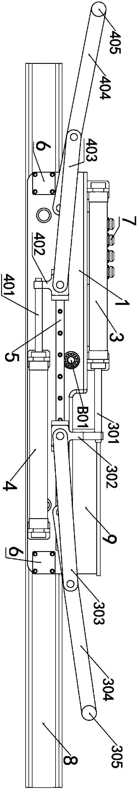
[0041] Such as figure 1 and Figure 4 As shown, a position-limiting intermittent transport device includes a car body 1 and a transport track 8, and is characterized in that the lower end of the car body 1 is provided with a walking chamber 2 used in conjunction with the transport track 8, and the car body A first pushing mechanism for pushing or braking the bogie is fixed on the body 1 . 1

[0042] Further, the first pushing mechanism includes a first hydraulic cylinder 3 fixed on the vehicle body 1, a sliding arm 5 and a first slider crank mechanism, and the first slider crank mechanism includes a first slider 302, a second A sliding rod 303, a first rotating rod 304 and a first push block 305, the first sliding block 302 is connected to the rod end of the first hydraulic rod 301 of the first hydraulic cylinder 3, and the first sliding block 302 covers Set on the sliding arm 5, one end of the first sliding rod 303 is connected to the first slider 302, and the other end of...

Embodiment 2

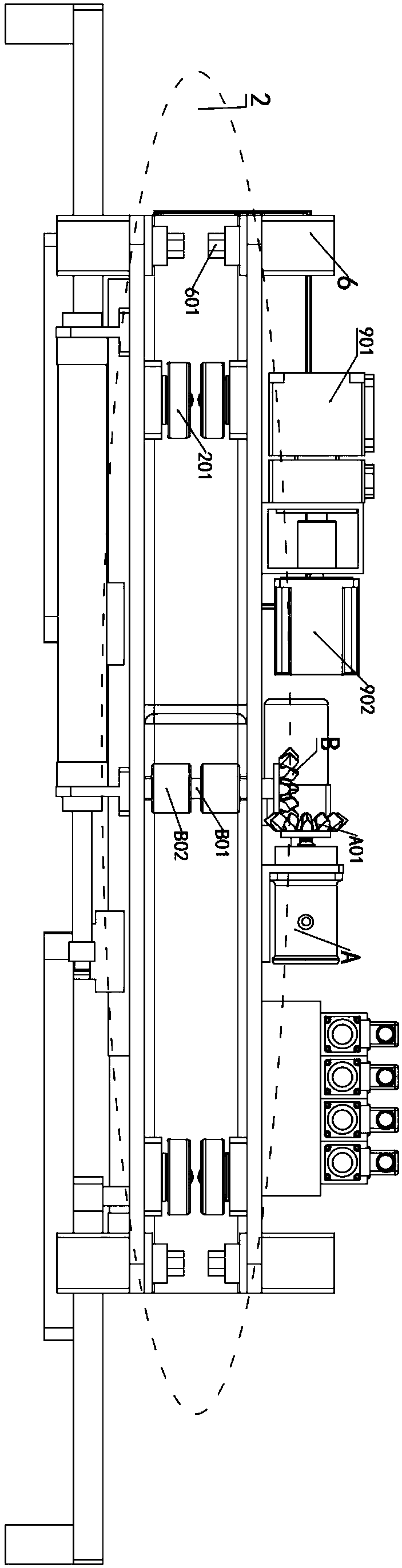
[0050] Such as figure 2 , image 3 and Figure 6 As shown, this embodiment is further optimized on the basis of Embodiment 1. Specifically, the transportation track 8 is set as an "I"-shaped structure, and the transportation track 8 includes a flange plate 801 and a web 802 .

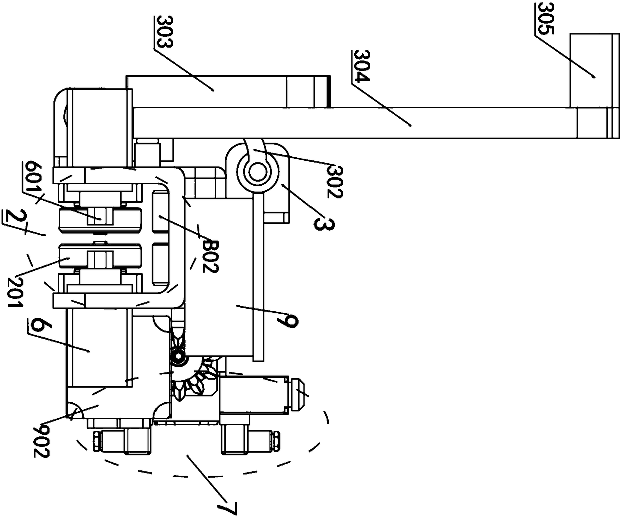
[0051] Further, a driving wheel B02 , a positioning wheel 201 and a brake lever 601 are arranged in the walking chamber 2 , and the driving wheel B02 is arranged in the walking chamber 2 near the upper end.

[0052] Further, the positioning wheels 201 are arranged symmetrically on opposite side walls of the walking cavity 2, and the distance between the two opposite positioning wheels 201 is greater than the thickness of the web 802, and the upper rim of the positioning wheels 201 The distance from the lower rim of the transmission wheel B02 is greater than the thickness of the flange plate 801 .

[0053] Further, the brake rod 601 is symmetrically arranged on the opposite side walls of the walking...

Embodiment 3

[0061] This embodiment is further optimized on the basis of embodiment 2, specifically, the brake 6 is powered by a hydraulic motor.

[0062] More optimally, two transmission wheels B02 , two pairs of positioning wheels 201 and two pairs of brake levers 601 are arranged in the walking chamber 2 .

[0063]More optimally, as Figure 5 As shown, the transmission motor A is connected to the driving wheel C, and the transmission rod B01 is connected to the driven wheel D, and the driving wheel C and the driven wheel D are connected through a transmission belt E to achieve the purpose of transmission.

[0064] When using the transportation device in this embodiment, the hydraulic motor injects hydraulic oil to make the brake lever 601 stretch out and clamp the web 802 of the transportation track 8. Since there is a certain space inside the hydraulic oil, a certain degree of elasticity can be allowed. Deformation, when the brake lever 601 needs a certain movement space, can be reali...


PUM


Abstract

The invention discloses an intermittent-type carrying device with a limiting function, and relates to the technical field of conveying devices, solving the problems of serious energy waste and low working efficiency during existing bogie maintenance. The intermittent-type carrying device comprises a trolley and a carrying track. A traveling cavity is formed in the lower end of the trolley. A firsthydraulic cylinder and a sliding arm are fixed to the trolley. The first hydraulic cylinder sleeves a first hydraulic rod. A first slider is connected to one end, located on the outer portion of thefirst hydraulic cylinder, the first hydraulic rod, and sleeves the sliding arm. A first sliding rod is connected to the first slider. A first rotating rod is connected to one end, away from the firstslider, of the first sliding rod. One end of the first rotating rod is connected to the trolley. A first push block is connected to the other end of the first rotating rod. The intermittent-type carrying device has the advantages of high carrying speed, high working efficiency, energy conservation and simplicity in operation.

Description

technical field [0001] The invention relates to the technical field of transportation devices, in particular to a position-limitable intermittent transportation device. Background technique [0002] With the rapid development of my country's rail transit, more and more rail vehicles are put into operation and use. It is estimated that by 2020, the national railway operating mileage will reach 120,000 kilometers, and the subway operating mileage will reach 6,000 kilometers. The maintenance and overhaul of rail vehicles pose new challenges. The bogie is one of the key components of rail vehicles. Therefore, it is necessary to overhaul the bogie regularly. [0003] During the maintenance process, the bogie needs to be transferred between different workstations and equipment. At present, there are mainly three types of transshipment lines that are widely used in the bogie maintenance workshops of each depot. The first is the ground circular track, which is operated by several m...

Claims


Application Information

Patent Timeline
Patent Type & Authority Applications(China)
IPC IPC(8): B61D15/00
CPCB61D15/00
Inventor 不公告发明人
Owner 成都岁生科技有限责任公司
Why Eureka
Try Eureka