Split forming mixed flow turbine

A mixed-flow and split-body technology, applied in the field of turbines, can solve problems affecting turbine performance, affecting turbine operation, weakening turbine output pressure and flow, and achieving the effect of improving air supply performance

Pending Publication Date: 2018-06-29
东莞市卓奇电子科技有限公司
View PDF0 Cites 0 Cited by
  • Summary
  • Abstract
  • Description
  • Claims
  • Application Information

AI Technical Summary

Problems solved by technology

Since the outer shroud is also running when it is working, there must be a certain gap between the outer shroud and the outer shroud, otherwise the outer wall of the outer shroud will rub against the outer shroud, affecting the operation of the turbine
However, since the air inlet air pressure of the turbine is low and the air outlet air pressure along the wheel is high, the high-pressure airflow on the air outlet side will leak back to the air inlet side through this gap, which will weaken the output of the turbine. Air pressure and flow affect the performance of the turbine

Method used


Image

  • Split forming mixed flow turbine
  • Split forming mixed flow turbine
  • Split forming mixed flow turbine

Examples


Embodiment Construction

[0026] In order to describe the technical content, structural features, and achieved effects of the present invention in detail, the following will be described in detail in conjunction with the embodiments and accompanying drawings.

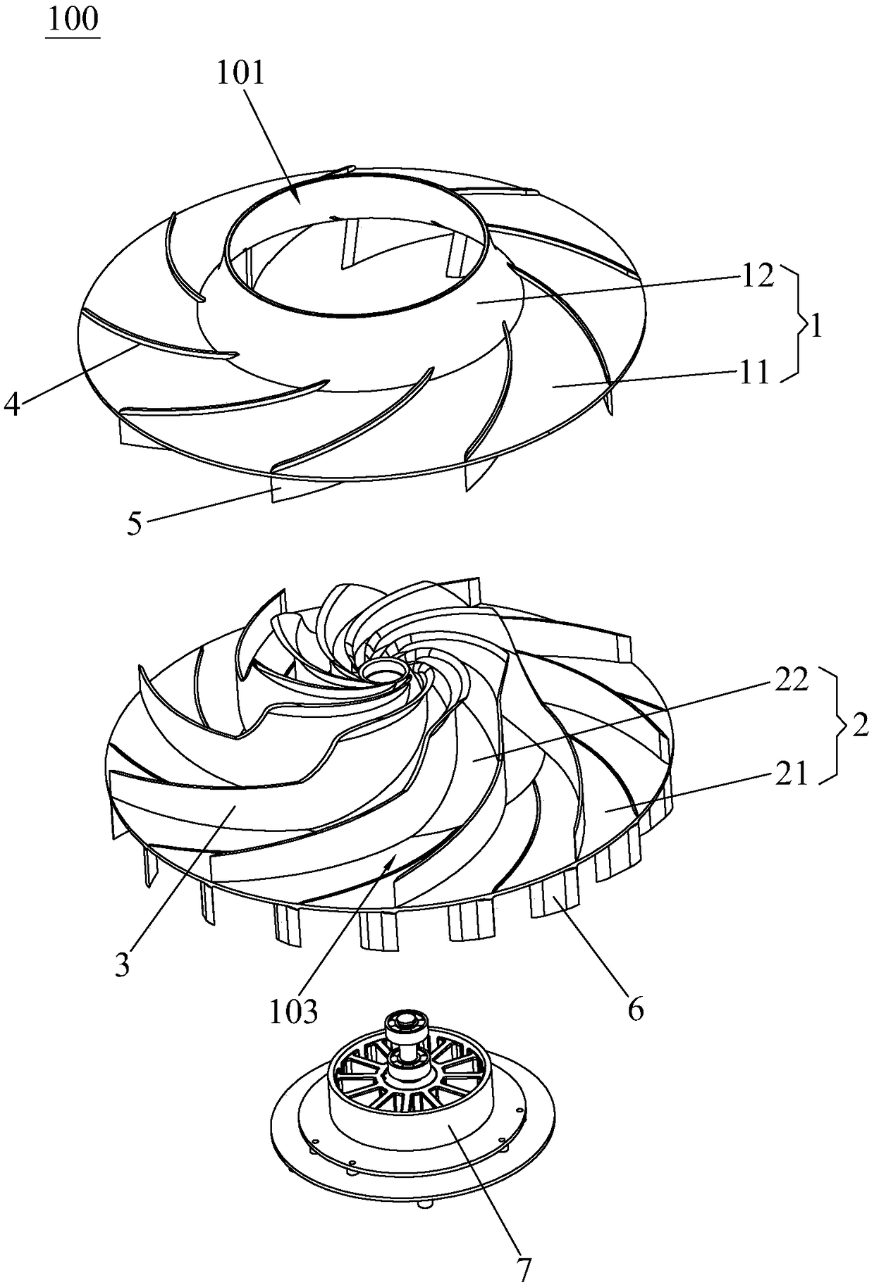
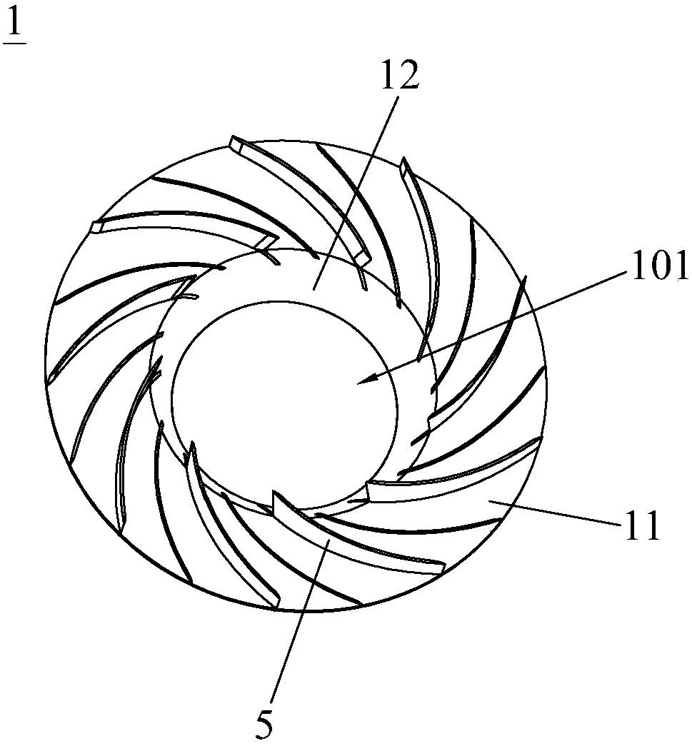
[0027] Such as Figure 1 to Figure 4 and Figure 7 As shown, the split-molded mixed-flow turbine 100 of Embodiment 1 of the present invention is installed in the outer cover 200, including the outer shroud 1 and the inner shroud 2, and the outer shroud 1 has an arc-shaped busbar. The first outer cover body 11, and the second outer cover body 12 formed by bending upwards from the inner edge of the first outer cover body 11; the inner shroud 2 has a first inner cover body 21 that is flat, and The inner edge of the first inner cover body 21 is bent upward to form a tapered second inner cover body 22 . There is a gap 201 between the outer shroud 1 and the outer shroud 200, and the inner wall of the outer shroud 1 and the outer wall of the inner sh...


PUM


Abstract

The invention discloses a split forming mixed flow turbine. The turbine comprises an outer flow guide cover and an inner flow guide cover, and a plurality of first blades are arranged around the central axis of any one of the inner wall of the outer flow guide cover and the outer wall of the inner flow guide cover, wherein the inner flow guide cover and the outer flow guide cover are arranged in acooperating mode; a flow guide air channel is formed among the first blades, the outer wall of the inner flow guide cover and the inner wall of the outer flow guide cover; and a plurality of second blades are arranged on the outer wall of the outer flow guide cover and around the central axis. The split forming mixed flow turbine has the advantages of being capable of preventing leakage and effectively improving the air supply performance.

Description

technical field [0001] The invention relates to a turbine, in particular to an anti-backflow turbine. Background technique [0002] Existing split turbines generally include an outer shroud and an inner shroud. When the turbine rotates, the air inlet in the center of the turbine will inhale the surrounding air. Under the guidance of the duct, it blows out from the air outlets around the turbine, and sends air outward along the inner wall of the outer cover. Since the outer shroud is also running during work, there must be a certain gap between the outer shroud and the outer shroud, otherwise the outer wall of the outer shroud will rub against the outer shroud, which will affect the operation of the turbine. However, since the air inlet air pressure of the turbine is low and the air outlet air pressure along the wheel is high, the high-pressure airflow on the air outlet side will leak back to the air inlet side through this gap, which will weaken the output of the turbine. ...

Claims


Application Information

Patent Timeline
Patent Type & Authority Applications(China)
IPC IPC(8): F04D29/28F04D29/44H02K21/22
CPCF04D29/28F04D29/444H02K21/22
Inventor 谢奇峰
Owner 东莞市卓奇电子科技有限公司
Why Eureka
Try Eureka