Automatic tail fiber storage device

An automatic storage and pigtail technology, applied in the fiber mechanical structure, light guide, optics, etc., can solve the problems of winding, large occupation area, pigtail extrusion, etc., to achieve the effect of convenient use, simple wiring, and protection of pigtails

Pending Publication Date: 2018-06-29
NINGBO TRANSMISSION & DISTRIBUTION CONSTR +1
View PDF0 Cites 1 Cited by
  • Summary
  • Abstract
  • Description
  • Claims
  • Application Information

AI Technical Summary

Problems solved by technology

However, such a metal box is heavy, expensive, takes up a large area, is complicated to install, and is limited by space, so the pigtails are often squeezed, cut, entangled, damaged, etc.

Method used


Image

  • Automatic tail fiber storage device
  • Automatic tail fiber storage device
  • Automatic tail fiber storage device

Examples


Embodiment Construction

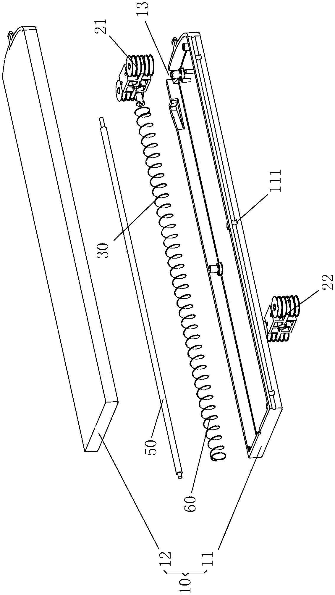
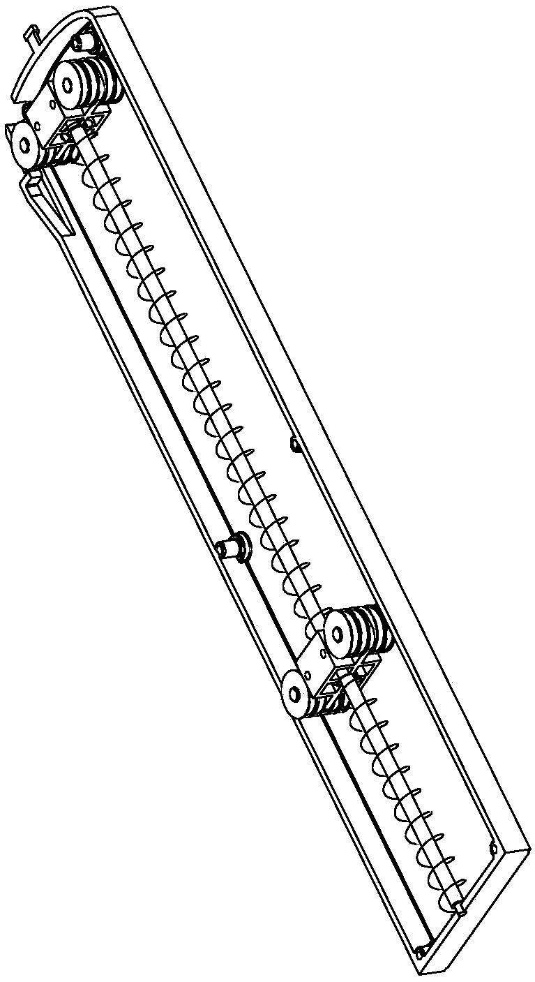
[0035] Examples, see figure 1 , figure 2 and Figure 4 Shown: a pigtail automatic storage device for storing a pigtail 100 having a connector 101, which is usually a standard connector.

[0036] in particular:

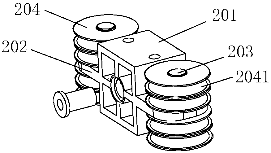
[0037] The pigtail automatic storage device includes: a box body 10, a fixed pulley block 21 and a movable pulley block 22, a first compression spring 30, a clamping device 40 and other components.

[0038] A side of the box body 10 is provided with a fiber inlet hole 13 for the pigtail 100 to pass through.

[0039] The fixed pulley block 21 is fixed on the right part of the inner cavity of the box body 10 , and the movable pulley block 22 is located in the inner cavity of the box body 10 and is positioned on the left side of the fixed pulley block 21 . Generally speaking, the fiber inlet hole 13 is located on the side of the cassette body 10 where the fixed pulley block 21 is located, that is, the right side of the cassette body 10 .

[0040] The first compressi...


PUM


Abstract

The invention discloses an automatic tail fiber storage device used for storing a tail fiber with a joint. The automatic tail fiber storage device comprises a box, a fixed pulley block, a movable pulley block, a first compression spring and a clamping device, wherein a tail fiber inlet hole is formed in one side of the box; the fixed pulley block is fixed on the right part of an inner cavity of the box, and the movable pulley block can be located in the inner cavity of the box in a bilaterally sliding manner and is located on the left side of the fixed pulley block; the first compression spring is matched with the movable pulley block to enable the movable pulley block to have a trend of leftward movement; the tail fiber enters the box via the tail fiber inlet hole, winds around the fixedpulley block and the movable pulley block and then penetrates out of the tail fiber inlet hole to the outside of the box; the joint of the tail fiber is located outside the box; the clamping device isdetachably or movably clamped on the tail fiber and located outside the box. The device has the advantages as follows: the device is convenient and simple to use and easy to operate.

Description

technical field [0001] The invention relates to the technical field of optical fiber storage, in particular to an automatic storage device for pigtails. Background technique [0002] In industries such as industry, civil, military, and electric power, the length control and storage of pigtails are involved in the use of residual fibers or pigtails after optical fiber fusion. In view of the particularity of optical fiber materials and the rigor of the fusion splicing process, the length of a single pigtail fiber prefabricated or spliced ​​in the factory is often fixed, such as 1 meter, 2 meters, etc., but the length of each pigtail fiber required by the equipment is different. After the optoelectronic equipment is connected, due to the constraints of site conditions and construction techniques, the remaining part, redundant part or unused end of the pigtail often hangs naturally on the spot and piles up in disorder. In this way, the dust and oil stains on site will affect th...

Claims


Application Information

Patent Timeline
Patent Type & Authority Applications(China)
IPC IPC(8): G02B6/44
CPCG02B6/4458
Inventor 丁健严江波黄云兵夏海亮沈浩高小丽陈因果
Owner NINGBO TRANSMISSION & DISTRIBUTION CONSTR
Why Eureka
Try Eureka