Improved bridge device

A technology for equipment and bridges, applied in the field of improved bridge equipment, can solve the problems that the contact rod cannot be automatically ejected, the power supply connection is unstable, the electrical facilities are damaged, etc., and achieves convenient and labor-saving extraction of the contact rod, simple and convenient locking operation, and safe power supply. stable effect

Inactive Publication Date: 2018-07-03
余丽君
View PDF0 Cites 0 Cited by
  • Summary
  • Abstract
  • Description
  • Claims
  • Application Information

AI Technical Summary

Problems solved by technology

[0002] At present, the construction of bridges is inseparable from electrical facilities. The power supply of electrical facilities is mainly to insert the contact rods connected with electrical facilities directly into the electrical connection holes of the electrical sockets. After the contact rod is inserted into the electrical connection hole, the contact rod can still be pulled out directly. When accidentally kicking and bumping into the cable connected between the contact rod and the electrical equipment, the contact rod will be detached from the electrical connection hole, resulting in damage to the electrical equipment. Sudden power failure, so the existing matching method has the risk of unstable power supply connection, which is easy to cause damage to electrical facilities due to sudden power failure, and the contact rod of the existing matching method cannot automatically pop up, when the contact rod is pulled out Need to apply a large force, pull out laborious

Method used


Image

  • Improved bridge device
  • Improved bridge device
  • Improved bridge device

Examples


Embodiment Construction

[0020] The preferred embodiments of the present invention will be described in detail below in conjunction with the accompanying drawings, so that the advantages and features of the present invention can be more easily understood by those skilled in the art, so as to define the protection scope of the present invention more clearly.

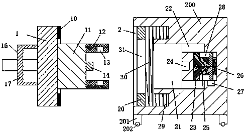
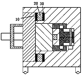
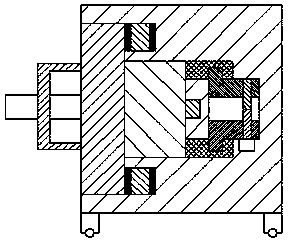
[0021] refer to Figure 1-4 The shown improved bridge equipment includes an electrical connector and an electrical socket, the electrical connector includes a first pin 1 and a second pin 11, and the second pin 11 is arranged on the right end surface of the first pin 1 Center, the center of the right end surface of the second bolt 11 is provided with a contact rod 14, the front and rear ends of the right end surface of the second bolt 11 are respectively provided with two connecting rods 12, and the inner end surfaces of the two connecting rods 12 Two locking holes 13 are respectively provided on the upper side, and an arc-shaped pressing block 1...


PUM


Abstract

The invention discloses an improved bridge device comprising an electrical connector and an electrical socket. The electrical connector comprises a first bolt and a second bolt. The second bolt is arranged at the center of a right end surface of the first bolt. The center of the right end surface of the second bolt is provided with a contact rod. The front and back ends of a right end surface of the second bolt are equally provided with two connection rods, and inner end surfaces of the two connecting rods are equally provided with two locking holes. Arc-shaped pressing blocks are arranged onthe right end surface of the first bolt and on the outer side of the second bolt. The electrical socket comprises a frame body. The improved bridge device has the advantages of a simple structure, good power supply stability, the safe and reliable operation of the whole device and reasonable structure design, even if someone accidentally hits a cable connected between the contact rod and an electrical appliance, the contact rod is not separated from the matching connection with an electrical connection hole, the locking and unlocking operations of the contact rod are simple and convenient, thesafety of bridge construction is improved, and the improved bridge device is suitable for popularization.

Description

technical field [0001] The invention relates to the field of bridges, in particular to an improved bridge device. Background technique [0002] At present, the construction of bridges is inseparable from electrical facilities. The power supply of electrical facilities is mainly to insert the contact rods connected with electrical facilities directly into the electrical connection holes of the electrical sockets. After the contact rod is inserted into the electrical connection hole, the contact rod can still be pulled out directly. When accidentally kicking and bumping into the cable connected between the contact rod and the electrical equipment, the contact rod will be detached from the electrical connection hole, resulting in damage to the electrical equipment. Sudden power failure, so the existing matching method has the risk of unstable power supply connection, which is easy to cause damage to electrical facilities due to sudden power failure, and the contact rod of the e...

Claims


Application Information

Patent Timeline
Patent Type & Authority Applications(China)
IPC IPC(8): H01R13/627H01R13/629H01R13/64H01R13/703
CPCH01R13/6275H01R13/629H01R13/64H01R13/7035
Inventor 余丽君严晓梦
Owner 余丽君
Why Eureka
Try Eureka