Novel power generation device

A wind power generation device, a new type of technology, applied in the direction of wind power generation, wind engine, wind motor combination, etc., can solve the problems of destroying the piezoelectric material itself, the price of the piezoelectric material is relatively expensive, and the economic value of electric energy is not large, so as to achieve the expansion of locking interval, increasing the scope of the locking area, and solving the effect of high wind speed

Pending Publication Date: 2018-07-10
HUAZHONG UNIV OF SCI & TECH
View PDF9 Cites 4 Cited by
  • Summary
  • Abstract
  • Description
  • Claims
  • Application Information

AI Technical Summary

Problems solved by technology

The above-mentioned energy harvester has a simple structure and can realize broadband energy harvesting. However, the energy harvester uses piezoelectric materials to achieve energy harvesting. Because the piezoelectric materials are affected by their own material properties, the electric energy generated by them is positively correlated with the deformation amplitude, and the low-amplitude deformation The relative economic value of the generated electric energy is not large, and the large amplitude and high-density vibration deformation will destroy the piezoelectric material itself, so the piezoelectric material is difficult to be effectively used in practical applications, and its output power is still low, and the frequency locking range is still Narrower, and the piezoelectric material is more expensive, and the preparation cost is higher

Method used


Image

  • Novel power generation device
  • Novel power generation device
  • Novel power generation device

Examples


Embodiment Construction

[0021] In order to make the object, technical solution and advantages of the present invention clearer, the present invention will be further described in detail below in conjunction with the accompanying drawings and embodiments. It should be understood that the specific embodiments described here are only used to explain the present invention, not to limit the present invention. In addition, the technical features involved in the various embodiments of the present invention described below can be combined with each other as long as they do not constitute a conflict with each other.

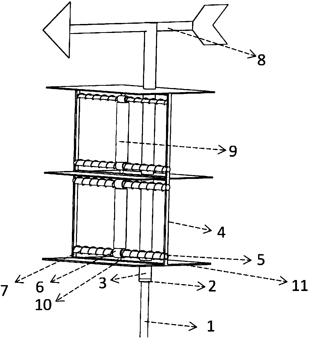
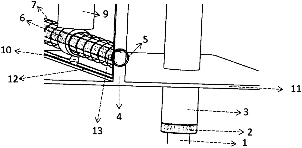
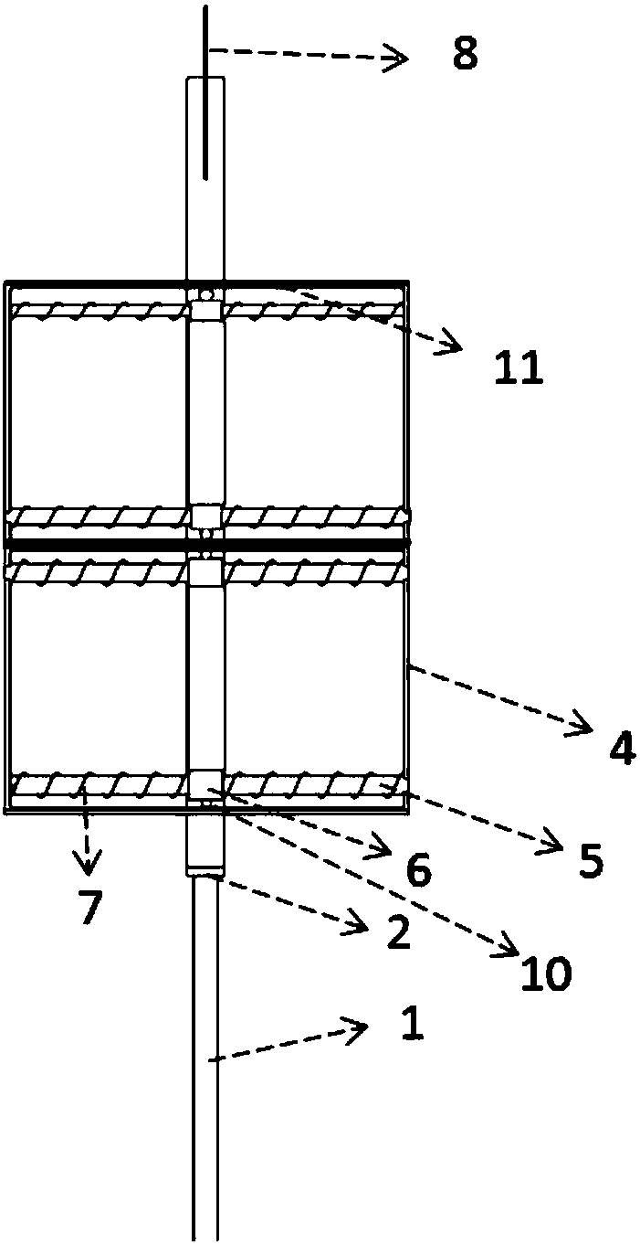
[0022] Such as figure 1 As shown, a new type of wind power generation device provided by the embodiment of the present invention includes a support frame 1, a rear-end rotation interference column 3 and a power generation unit, wherein the bottom of the support frame 1 is connected to the ground and mainly serves as a support for the overall structure. The lower end of the rear-end rotation int...


PUM


Abstract

The invention belongs to the field of wind power generation devices and particularly discloses a novel power generation device. The novel power generation device comprises a supporting frame, a rear-end rotary interference column body and a power generation unit. The rear-end rotary interference column body is rotatably connected with the supporting frame. A weather vane is mounted at the upper end of the rear-end rotary interference column body. The power generation unit is mounted on the rear-end rotary interference column body. The power generation unit comprises two supporting plates and atwo-side fixed support arranged between the two supporting plates. Two power generation modules are arranged between the two side of the two-side fixed support. Each power generation module comprisessleeves, coils are arranged in the sleeves, cylindrical magnets are arranged outside the sleeves, the two sides of the cylindrical magnets are connected with the two sides of the two-side fixed support through springs and are limited through grooves formed in the supporting plates. Vibration cylinders are arranged between the cylindrical magnets of the two sets of power generation modules. The novel power generation device can increase the vibration amplitude and the frequency locking interval of the vibration cylinders and is large in output power and good in environmental adaptability.

Description

technical field [0001] The invention belongs to the field of wind power generation devices, and more specifically relates to a novel wind power generation device. Background technique [0002] Wind energy is a clean energy that is widely distributed in nature. With the rapid development of science and technology, the current utilization of this kind of energy accounts for a large proportion of the total energy consumption of human beings. The most common use of wind energy is that the wind blows through the blades to move the turbines, which are then converted into electrical energy through electromagnetic conversion. However, if the turbine wants to obtain considerable energy, it needs a relatively large start-up flow rate for a long time, and the perennial wind speed in most areas cannot meet this condition. On the one hand, it causes a lot of waste of wind energy resources and hinders the use of wind energy. Therefore, the current research on the utilization of low wind...

Claims


Application Information

Patent Timeline
Patent Type & Authority Applications(China)
IPC IPC(8): F03D9/25F03D13/20F03D17/00F03D80/00
CPCF03D9/25F03D13/20F03D17/00F03D80/00F05B2260/96Y02E10/728Y02E10/72
Inventor 代胡亮王琳张岚斌周小文陈伟江天力林时想
Owner HUAZHONG UNIV OF SCI & TECH
Why Eureka
Try Eureka