Lock and anti-theft door

A lock and lock body technology, applied in the field of smart locks, can solve the problems of lock core intelligence and poor anti-theft performance, and achieve the effects of improving anti-theft performance, reducing costs and compact structure

Pending Publication Date: 2018-07-17
深圳市罗漫斯智能家居有限公司
6 Cites 1 Cited by

AI-Extracted Technical Summary

Problems solved by technology

[0005] The technical problem to be solved by the present invention is to provide a lock to solve the problems of poor int...

Method used

[0032] Preferably, the electric screw mechanism 20 includes three screw rods 21 arranged s...

Abstract

The invention relates to the field of intelligent locks, in particular to a lock and an anti-theft door. The lock comprises a lock body, an electric screw rod mechanism and an electric inclined tonguemechanism, wherein the electric screw rod mechanism and the electric inclined tongue mechanism are arranged on the lock body, and the electric screw rod mechanism comprises at least one spiral rod which is arranged on the first end face of the lock body in a penetrating mode and penetrates through the first end face of the lock body in a penetrating mode; and a first driving assembly for drivingthe screw rod to rotate and contract, the electric inclined tongue mechanism comprises an inclined tongue which is telescopically arranged on the first end face of the lock body in a penetrating modeand a second driving component which drives the inclined tongue to retract. The electric screw rod mechanism and the electric inclined tongue mechanism are arranged on the lock, so that intelligent opening and electric starting are achieved, the sliding mode is replaced by the mode that the screw rod rotates and retracts, so that the anti-theft performance is greatly improved, the structure is compact, the occupied space is small, and the cost is reduced.

Application Domain

Burglary protectionNon-mechanical controls +1

Technology Topic

Anti theftMechanical engineering

Image

  • Lock and anti-theft door
  • Lock and anti-theft door
  • Lock and anti-theft door

Examples

  • Experimental program(1)

Example Embodiment

[0028] The preferred embodiments of the present invention will now be described in detail with reference to the accompanying drawings.
[0029] like figure 1 As shown, the present invention provides a preferred embodiment of a lock.
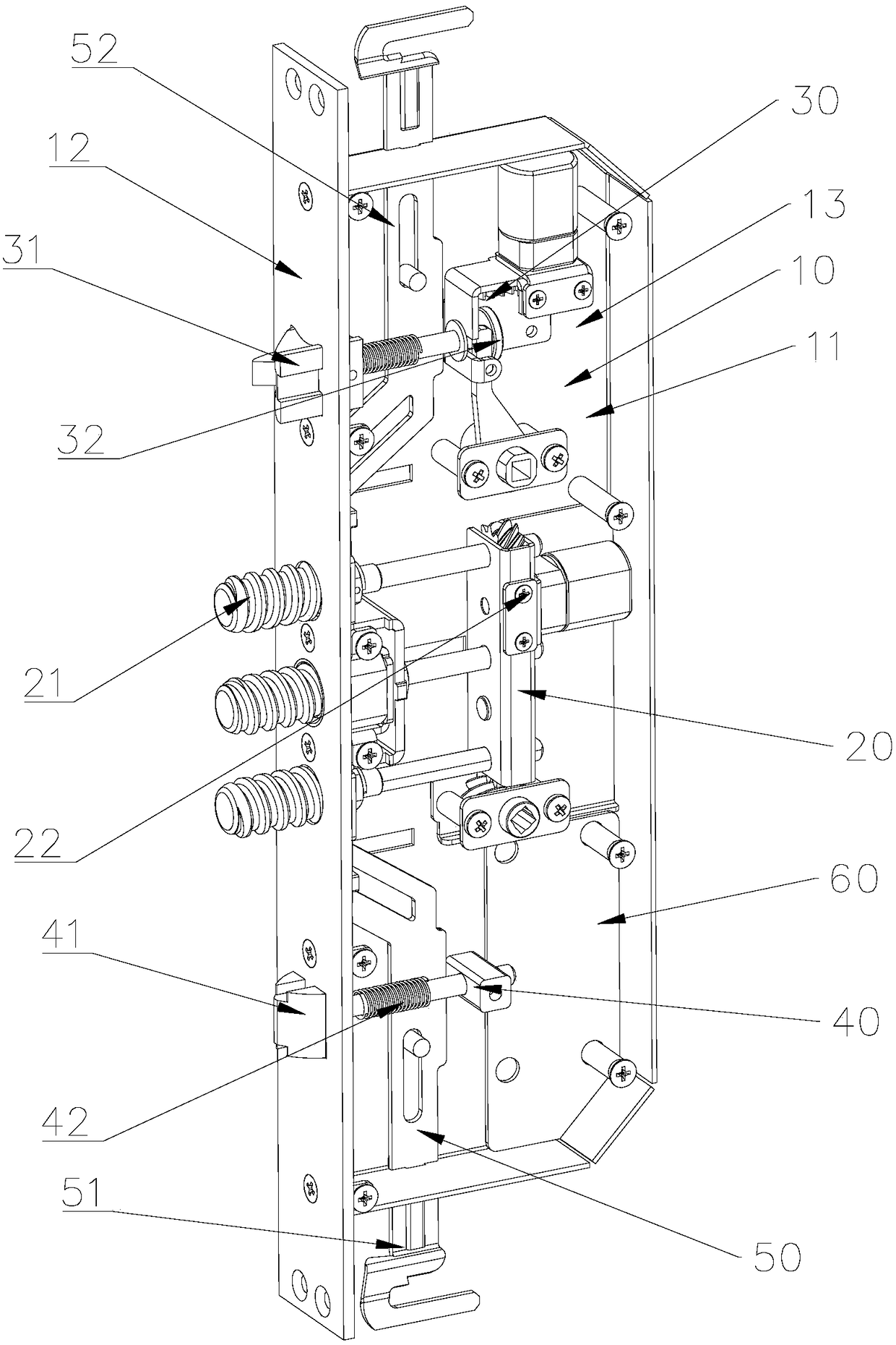
[0030] A lock, the lock includes a lock body 10, and an electric screw rod mechanism 20 and an electric oblique tongue mechanism 30 arranged on the lock body 10. The screw rod 21 on the first end surface 12 of the lock body 10, and the first drive assembly 22 that drives the screw rod 21 to rotate and extend, the electric oblique tongue mechanism 30 includes a oblique tongue 31 telescopically penetrated on the first end surface 12 of the lock body 10 and the second drive assembly 32 that drives the oblique tongue 31 to retract.
[0031] Specifically, the lock body 10 includes a casing, and a cavity 11 disposed in the casing. The casing includes a first end face 12 and a second end face 13 , and the screw rod 21 and the oblique tongue 31 pass through the first end face of the casing On one end face 12; and, the electric screw rod mechanism 20 and the electric oblique tongue mechanism 30 are both arranged in the cavity 11 and fixed on the housing; It penetrates on the first end surface 12 of the lock body 10 to perform telescopic movement to realize screw locking. Driven by the second drive assembly 32, the oblique tongue 31 penetrates through the first end surface 12 of the lock body 10 to retract and move. .
[0032] Preferably, the electric screw rod mechanism 20 includes three screw rods 21 arranged side by side, preferably three, to achieve multiple locking and increase the anti-theft effect.
[0033] In this embodiment, the lock further includes a two-way oblique tongue mechanism 40 , and the two-way oblique tongue mechanism 40 includes a two-way oblique tongue 41 telescopically penetrated on the first end surface 12 of the lock body 10 and connected to the two-way oblique tongue 41 the third elastic member 42 .
[0034] Specifically, the bidirectional oblique tongue mechanism 40 further includes a bidirectional oblique tongue 41 rod connected to the bidirectional oblique tongue 41 , and a fixing block 223 arranged at the end of the bidirectional oblique tongue 41 rod, and the entire bidirectional oblique tongue mechanism 40 is fixed by the fixing block 223 On the second end face 13 of the housing; a spring is sleeved on the rod of the bidirectional oblique tongue 41 , and both ends of the spring abut against the bidirectional oblique tongue 41 and the fixing block 223 respectively.
[0035] Preferably, the electric screw rod mechanism 20 is arranged between the electric oblique tongue mechanism 30 and the bidirectional oblique tongue mechanism 40; and the longitudinal direction is arranged on the same straight line.
[0036] In this embodiment, the electric oblique tongue mechanism 30 further includes a fixing bracket 33 fixed with the lock body 10 , a oblique tongue rod 311 connected with the oblique tongue 31 , and an elastic reset mechanism for pushing the oblique tongue 31 forward. The second drive assembly 32 drives the oblique tongue 31 to move backward, that is, to move toward the inside of the cavity 11 of the lock body 10 , and after the second drive assembly 32 is reset, the elastic reset mechanism drives the oblique tongue 31 to move forward, that is, the reverse of the backward movement. .
[0037] The elastic reset mechanism is preferably a spring 312 sleeved on the oblique tongue rod 311 , and both ends of the spring 312 abut against the oblique tongue 31 and the fixing bracket 33 respectively.
[0038] In this embodiment, the cavity 11 of the lock body 10 is further provided with a circuit board 60 . The circuit board 60 is provided with a circuit structure for controlling the operation of the lock, and is respectively connected with the first drive assembly 22 and the second drive assembly 32 connected to control the first drive assembly 22 and the second drive assembly 32 to work.
[0039] like figure 2 and image 3 As shown, the present invention provides a preferred embodiment of a security door.
[0040] An anti-theft door, the anti-theft door includes a door leaf 220 and a door frame 210, a lock is installed on the door leaf 220, the door frame 210 is provided with a door buckle plate 100, and the door buckle plate 100 includes a screw door buckle frame 101, The first door buckle hole (not shown) is matched with the screw rod 21 of the lock, and the second door buckle hole 110 is matched with the oblique tongue 31 of the lock. With the matching door lock frame hole 1011, the screw rod 21 of the lock extends through the first door lock hole and into the door lock frame hole 1011.
[0041] And, the door buckle plate 100 is further provided with a third door buckle hole 120 that cooperates with the two-way oblique tongue mechanism 40.
[0042]Specifically, an operation example of the anti-theft door is provided: when the door leaf 220 is closed to the door frame 210, the oblique tongue 31 first retracts the lock due to the action of the door buckle plate 100, and extends the lock and extends into the second door buckle after closing. The door leaf 220 can be opened from the door frame 210 when the door leaf 220 is opened from the door frame 210 by retracting the latch 31 back into the lock set through the second drive assembly 32 under control (through the lock electronic button or the remote control lock set circuit) in the hole 110; and when the door leaf 220 is closed After reaching the door frame 210, the screw rod 21 is rotated and extended to the lock set through the first drive assembly 22 under the control (through the electronic button of the lock set or the remote control of the lock set circuit), and extends into the screw rod door catch frame through the first door catch hole In the door catch frame hole 1011 of 101, the anti-lock of the lock is realized; and, under the control (through the electronic button of the lock or the remote control of the lock circuit), the screw rod 21 is rotated and retracted to the lock through the first drive assembly 22, so as to release the anti-lock.
[0043] Further, when the door leaf 220 is folded to the door frame 210, the two-way oblique tongue mechanism 40 realizes that the door leaf 220 is stably closed into the door frame 210, and aligns the oblique tongue 31 and the screw rod 21 with the corresponding hole positions to improve the stability of the anti-theft door. .
[0044] like Figure 4 to Figure 6 As shown, the present invention provides a preferred embodiment of an electric screw mechanism.
[0045] The free end 211 of the screw rod 21 is provided with an external thread, and the connecting end 212 of the screw rod 21 is connected with the first drive assembly 22; 223 is provided with a threaded hole, and the free end 211 of the screw rod 21 is threadedly connected to the fixing block 223 through the threaded hole.
[0046] In this embodiment, the first drive assembly 22 includes a first drive motor 221 , a main gear 2221 and a sub gear 2222 , the main gear 2221 is connected to the rotating rod 342 of the first drive motor 221 , and the sub gear 2222 Coaxially disposed with the connecting end 212 of the screw rod 21 , the main gear 2221 and the secondary gear 2222 are meshed with each other.
[0047] Further, the secondary gear 2222 is rotatably mounted on the fixed seat 224, the primary gear 2221 is drivingly connected with the first drive motor 221, and meshes with the secondary gear 2222; the connecting end 212 of the screw rod 21 is coaxially connected with the secondary gear 2222. Among them, the main gear 2221 and the secondary gear 2222 are both helical gears, and the helical gears have high meshing precision and low transmission noise. Also, the main gear 2221 and the secondary gear 2222 may also be gears of other shapes, such as spur gears, bevel gears, and the like.
[0048] In order to enable the secondary gear 2222 to drive the screw rod 21 to rotate without hindering the expansion and contraction of the screw rod 21, a non-circular special-shaped hole 22221 is formed in the center of the secondary gear 2222. The outer contour of the connecting end 212 of the screw rod 21 and the special-shaped hole 22221 is matched, and is slidably inserted into the special-shaped hole 22221. Please refer to figure 2 , the connecting end 212 of the screw rod 21 is cut to form a cutting plane, and a boss surface matched with the cutting plane is formed in the special-shaped hole 22221, that is, the screw rod 21 can rotate with the secondary gear 2222 and can slide relative to the secondary gear 2222.
[0049] In this embodiment, the electric screw rod mechanism 20 further includes a first emergency opening assembly 23, and the first emergency opening assembly 23 includes a first rotating part (not shown) extending out of the lock body 10 and a An emergency gear 231 connected to the rotating part, the emergency gear 231 is meshed with the main gear 2221 or the secondary gear 2222 .
[0050] Specifically, one end of the first rotating part is rotatably connected with the emergency gear 231 , and the other end of the first rotating part protrudes from the second end surface 13 of the casing.
[0051] like Figure 7 to Figure 9 As shown, the present invention provides a preferred embodiment of an electric tongue mechanism.
[0052] The second drive assembly 32 and the oblique tongue rod 311 are both disposed on the fixed bracket 33. The second driving assembly 32 includes a moving part 323 that drives the oblique tongue rod 311 to move backward, and the oblique tongue 31 follows the oblique tongue rod. 311 moves while moving.
[0053] In this embodiment, the end portion of the oblique tongue rod 311 includes a first extension portion 3111 , the moving portion 323 includes a rack 32301 that moves along the moving direction of the oblique tongue rod 311 , and is provided at the end of the rack 32301 The second extension part 3231 of the second extension part 3231 abuts on the inner side of the first extension part 3111, and the second drive assembly 32 includes a second drive motor 321 and a motor gear 322 meshing with the rack 32301, so The motor gear 322 drives the rack 32301 to move under the driving of the second drive motor 321, and drives the oblique tongue rod 311 to move backward through the cooperation of the second extension portion 3231 and the first extension portion 3111.
[0054] Preferably, the first extension portion 3111 extends in the transverse direction of the oblique tongue rod 311 , and the second extension portion 3231 extends in the transverse direction of the moving structure. Preferably, the oblique tongue rod 311 is a pin structure, and the pin cap thereof is the first extension portion 3111 .
[0055] Specifically, the second driving motor 321 rotates and drives the motor gear 322 to rotate, the motor gear 322 rotates on the rack 32301, and drives the moving structure to move back and forth along the setting direction of the rack 32301, and when the moving structure moves backward, the The second extension portion 3231 abuts against the inner side of the first extension portion 3111, and drives the oblique tongue rod 311 to move backward. And, when the moving structure moves forward, the second extension portion 3231 is driven to return to the original position. The first extension portion 3111 is pushed back to the original position by the elastic force of the spring due to the lack of the pushing force of the second extension portion 3231 .
[0056] In this embodiment, the electric latch mechanism 30 further includes a second emergency opening assembly, and the emergency opening assembly includes a second rotating part 341 extending out of the lock body 10 and rotating around the second rotating part 341 The rotation rod 342 is provided, and the other end of the rotation rod 342 abuts against the inner side of the first extension part 3111 .
[0057] like figure 1 , Figure 4 and Figure 5 , the present invention provides a preferred embodiment of a heaven and earth pole.
[0058] The electric screw rod mechanism 20 further includes a screw rod 21 bracket fixedly arranged with the screw rod 21, a boss is provided on the screw rod 21 bracket, and the lock also includes a sky rod 50, and the sky rod 50 includes a The inclined groove, the boss of the support of the screw rod 21 is sleeved on the inclined groove, and the lock body 10 also includes a fixing rod sleeved on the inclined groove of the heaven and earth rod 50 .
[0059] Specifically, the corresponding positions of the door leaf 220 and the door frame 210 are provided with corresponding holes, and the sky pole 50 is driven by the screw rod 21. The ground rod 52 of 50 descends and extends through the door leaf 220 into the door frame 210. At this time, the screw rod 21 extends into the door frame 210, and the boss of the support of the screw rod 21 is clamped at the lower end of the oblique groove of the sky rod 51 and the ground rod 52. The upper end of the chute; on the contrary, driven by the screw rod 21, the sky rod 51 of the heaven and earth rod 50 descends and retracts into the lock, and the ground rod 52 of the heaven and earth rod 50 rises and retracts into the lock. At this time, the screw rod 21 is retracted into the lock, and the boss of the bracket of the screw rod 21 is clamped on the upper end of the oblique groove of the sky rod 51 and the lower end of the low rod oblique groove.
[0060] The above descriptions are only the best embodiments of the present invention and are not intended to limit the scope of the present invention. All equivalent changes or modifications made according to the scope of the patent application of the present invention are all covered by the present invention.

PUM

no PUM

Description & Claims & Application Information

We can also present the details of the Description, Claims and Application information to help users get a comprehensive understanding of the technical details of the patent, such as background art, summary of invention, brief description of drawings, description of embodiments, and other original content. On the other hand, users can also determine the specific scope of protection of the technology through the list of claims; as well as understand the changes in the life cycle of the technology with the presentation of the patent timeline. Login to view more.

Similar technology patents

Multiplex anti-theft lock

ActiveCN103573035AImprove anti-theft performanceSafe and reliable lock structure
Owner:烟台三环制锁科技有限公司

Intelligent security door

Owner:丽水亿智工业设计有限公司

Key, lock cylinder and electromagnetic lock

Owner:利泰五金制品(东莞)有限公司

Novel diamond mesh anti-theft lifting screen window

Owner:山西唯美诺建筑装饰工程有限公司

Classification and recommendation of technical efficacy words

  • Improve anti-theft performance
  • compact structure

Lock core

Owner:ZHONGSHAN CITY JIXIN CORE LOCK CO LTD

Using method of multi-lock container password anti-theft lock

InactiveCN102011525AImprove anti-theft performance
Owner:南通睿祺智能科技有限公司
Why Eureka
Try Eureka