Drilling steering tool and drilling system

A drilling and tool technology, applied in the field of drilling steering tools and drilling systems, can solve the problems of unreachable drilling effect, poor bit tilting effect, poor bending effect of rotating shaft, etc.

Active Publication Date: 2019-12-20
BC P INC CHINA NAT PETROLEUM CORP +1
View PDF5 Cites 0 Cited by
  • Summary
  • Abstract
  • Description
  • Claims
  • Application Information

AI Technical Summary

Problems solved by technology

The driving mechanism in the existing rotary steerable drilling system generally adopts an eccentric ring, and the rotating shaft is sleeved in the eccentric ring. The eccentric ring has a certain restrictive effect on the bending of the rotating shaft, and the bending effect of the rotating shaft is poor, resulting in the drill bit. The inclination effect is not good, and the drilling effect cannot meet expectations

Method used


Image

  • Drilling steering tool and drilling system
  • Drilling steering tool and drilling system
  • Drilling steering tool and drilling system

Examples


Embodiment 1

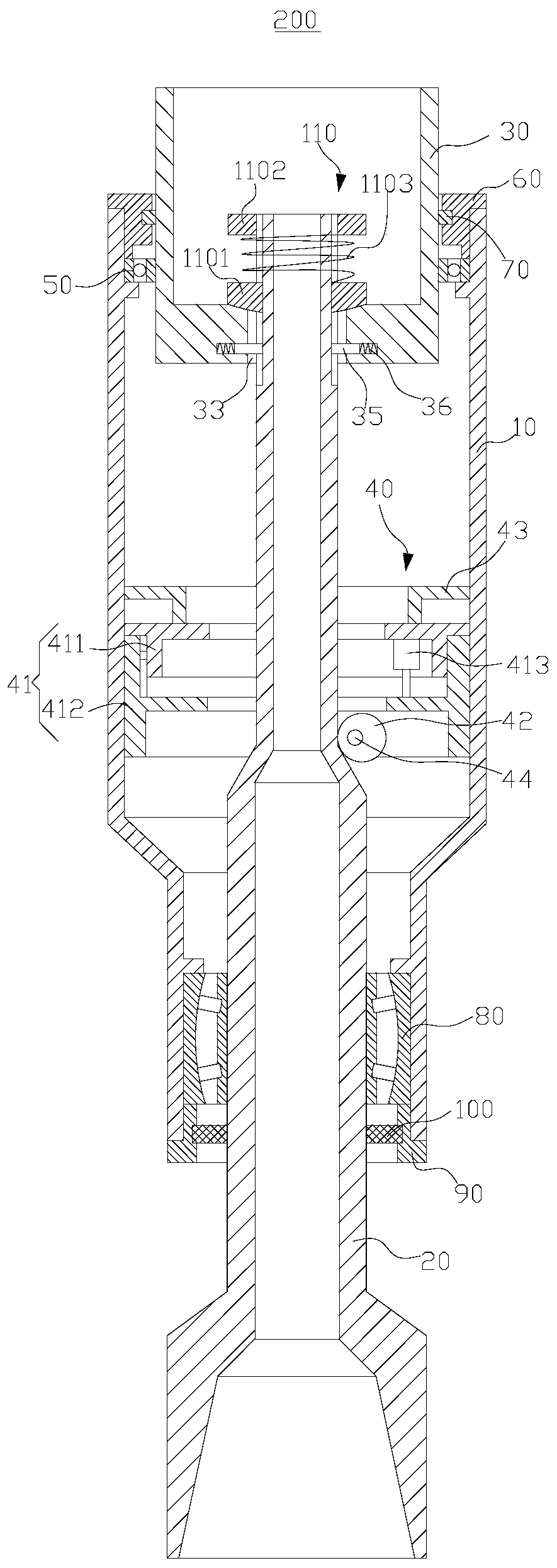
[0047] Such as figure 1 As shown, the present embodiment provides a drilling guide tool 200, comprising a hollow casing 10, a rotating shaft 20, a hollow drill collar 30 and a driving mechanism 40, the rotating shaft 20 is rotatably arranged in the hollow casing 10, and the hollow drill collar 30 and The rotating shaft 20 is connected, and the hollow drill collar 30 can rotate together with the rotating shaft 20 . The driving mechanism 40 is arranged in the hollow jacket 10 , and the driving mechanism 40 is used to bend the rotating shaft 20 .

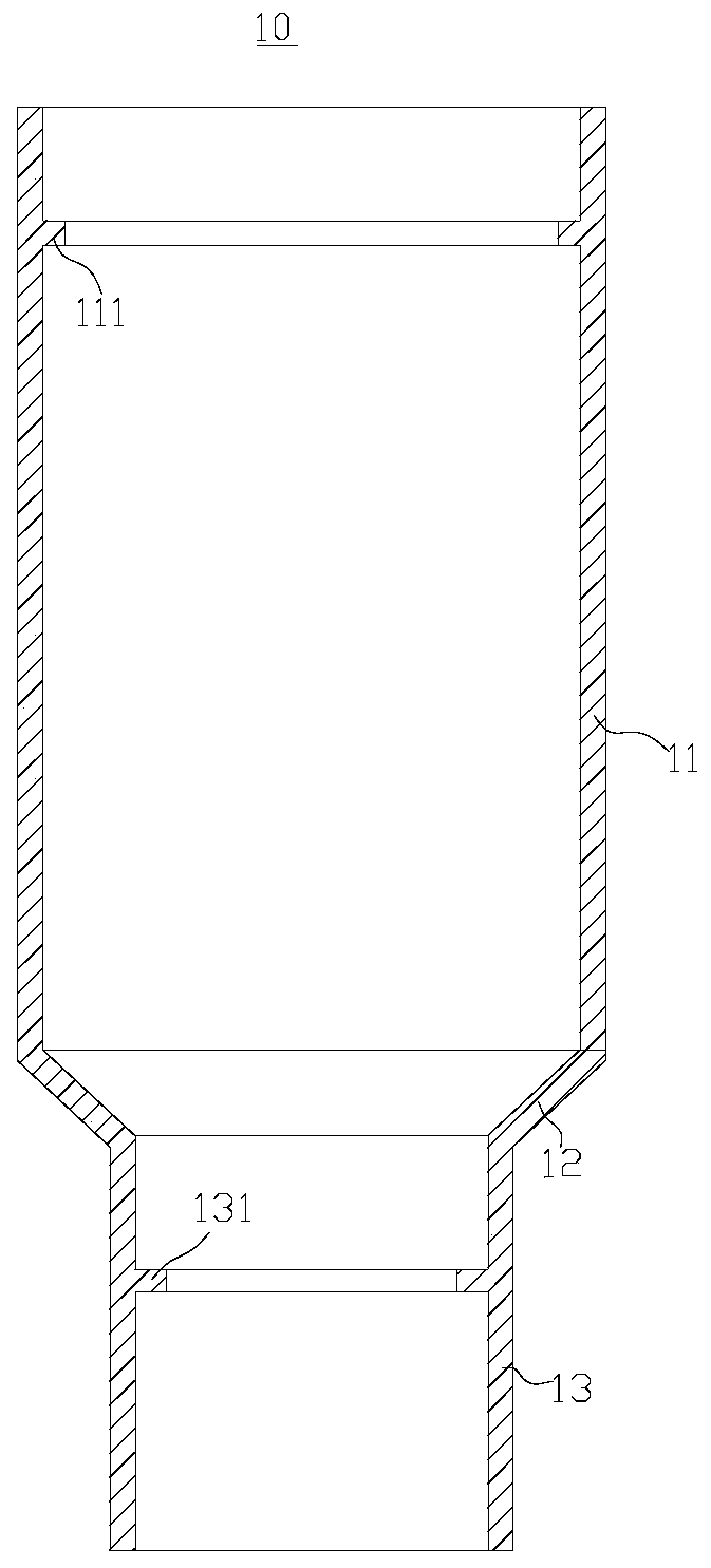
[0048] Such as figure 2 As shown, the hollow jacket 10 is a hollow structure with two ends open, and its cross-section is ring-shaped. The hollow casing 10 includes a coaxially arranged first cylindrical body 11, a transition body 12 and a second cylindrical body 13, the first cylindrical body 11 and the second cylindrical body 13 are connected through the transition body 12, and the inner diameter of the first cylindrical body 11 is...

Embodiment 2

[0061] Such as Figure 8 As shown, this embodiment provides a drilling system 300, including a drilling rig 310, a drill string 320, a drill bit 330 and the drilling steering tool 200 in the above-mentioned embodiments.

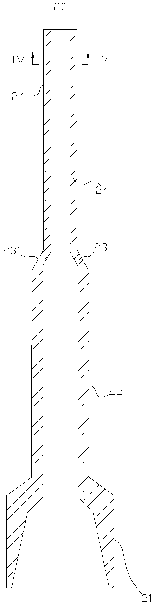
[0062] The drilling rig 310 is placed on the ground, one end of the drill string 320 is connected with the drilling machine 310, the drill string 320 extends into the borehole below the ground, the other end of the drill string 320 is connected with the hollow drill collar 30 in the drilling guide tool 200, the drill bit 330 is connected with the The shaft head 21 of the rotating shaft 20 is connected. When the drilling rig 310 is working, the drill string 320 will drive the hollow drill collar 30 and the rotating shaft 20 to rotate, thereby rotating the drill bit 330 to complete the drilling action.


PUM


Abstract

The invention provides a well drilling guide tool and a well drilling system, and belongs to the field of well drilling tools. The well drilling guide tool comprises a hollow outer sleeve, a rotatingshaft, a hollow drill collar and a driving mechanism. The outer side of the rotating shaft is sleeved with the hollow outer sleeve, and the rotating shaft is connected with the hollow outer sleeve through a spherical bearing. The hollow drill collar is rotatably arranged in the hollow outer sleeve, and the hollow drill collar is supported on the rotating shaft. The driving mechanism comprises a rotating body, an eccentric wheel, a first driving device and a second driving device, wherein the rotating body is rotatably arranged in the hollow outer sleeve, the eccentric wheel is connected with the rotating body in a rotating mode, the first driving device is used for driving the rotating body to rotate around the rotating shaft relative to the hollow outer sleeve, and the second driving device is used for driving the eccentric wheel to rotate relative to the rotating body. The rotating of the eccentric wheel relative to the rotating body can bend the rotating shaft. According to the welldrilling guide tool, the eccentric wheel rotates to bend the rotating shaft, the eccentric wheel is in line contact with the rotating shaft, and the eccentric wheel does not limit the bending of therotating shaft.

Description

technical field [0001] The invention relates to the field of drilling tools, in particular to a drilling guide tool and a drilling system. Background technique [0002] The rotary steerable drilling system relies on the driving mechanism between the hollow casing and the rotating shaft to bend the rotating shaft, thereby providing the drill bit with an inclination angle that is inconsistent with the wellbore axis to produce a steering effect. The driving mechanism in the existing rotary steerable drilling system generally adopts an eccentric ring, and the rotating shaft is sleeved in the eccentric ring. The eccentric ring has a certain restrictive effect on the bending of the rotating shaft, and the bending effect of the rotating shaft is poor, resulting in the drill bit. The inclination effect is not good, and the drilling effect cannot meet expectations. Contents of the invention [0003] The purpose of the present invention is to provide a drilling steering tool to imp...

Claims


Application Information

Patent Timeline
Patent Type & Authority Patents(China)
IPC IPC(8): E21B7/04
CPCE21B7/04
Inventor 刘乃震赵齐辉卢毓周李永和张磊吴琼邵珊张美君董智伟余凯乔纳
Owner BC P INC CHINA NAT PETROLEUM CORP
Why Eureka
Try Eureka