Display panel and method for improving display panel Newton ring
A technology for display panels and Newton rings, applied in semiconductor devices, electrical components, circuits, etc., to achieve the effect of improving Newton ring phenomenon and improving picture quality
- Summary
- Abstract
- Description
- Claims
- Application Information
AI Technical Summary
Problems solved by technology
Method used
Image
Examples
Embodiment 1
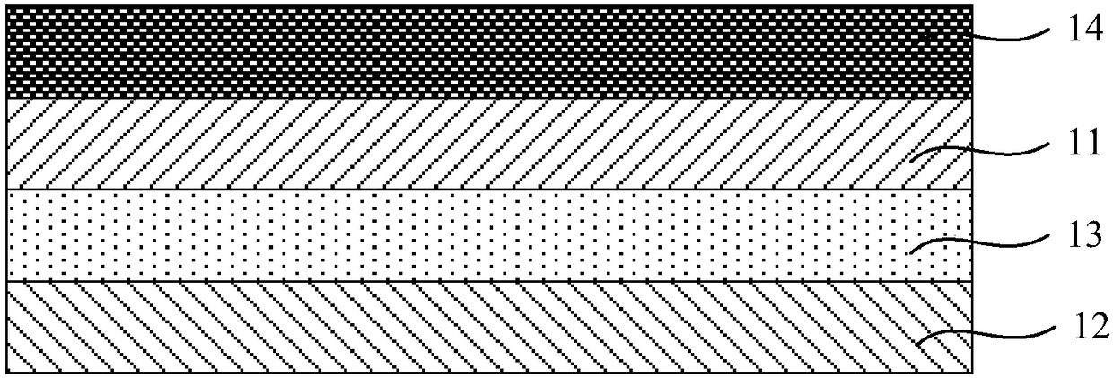
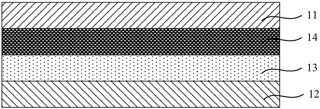
[0030] Please refer to Figure 1a and Figure 1b , which is a schematic structural diagram of the display panel provided by Embodiment 1 of the present invention. Such as Figure 1a and Figure 1b As shown, the display panel includes a first substrate 11 and a second substrate 12 oppositely arranged, and a light-emitting unit 13 is arranged between the first substrate 11 and the second substrate 12, and the light emitted by the light-emitting unit 13 propagates Pass through the first substrate 11 when going to the outside of the display panel, the upper surface or the lower surface of the first substrate 11 is coated with an optically polymerized organic material 14, and the optically polymerized organic material 14 is refracted when irradiated by laser light The refractive index changes, and the change in the refractive index is related to the wavelength of the laser light.
[0031] exist Figure 1a In, the upper surface of the first substrate 11 is coated with an optica...
Embodiment 2
[0047] Please refer to Figure 2a and Figure 2b , which is a schematic structural diagram of the display panel provided in Embodiment 2 of the present invention. like Figure 2a and Figure 2b As shown, the display panel includes a display screen and a touch screen 25 located on the display screen, the display screen includes a first substrate 21 and a second substrate 22 that are oppositely arranged, and the first substrate 21 and the second substrate A light emitting unit 23 is disposed between the substrates 22 , and the touch screen 25 is disposed on the first substrate 21 . The light emitted by the light emitting unit 23 passes through the first substrate 21 and the touch screen 25 when it propagates to the outside of the display panel, and the upper surface or the lower surface of the first substrate 21 is coated with an optically polymerized organic material 24. The refractive index of the optically polymerized organic material 24 changes when irradiated by laser l...
Embodiment 3
[0057] Please refer to Figure 3a and Figure 3b , which is a schematic structural diagram of the display panel provided by Embodiment 3 of the present invention. like Figure 3a and Figure 3b As shown, the display panel includes a display screen and a touch screen 35 located on the display screen, the display screen includes a first substrate 31 and a second substrate 32 that are oppositely arranged, and the first substrate 31 and the second substrate 32 A light-emitting unit 33 is arranged between the substrates 32, and the light emitted by the light-emitting unit 33 passes through the first substrate 31 and the touch screen 35 when propagating to the outside of the display panel, and paints on the upper surface or the lower surface of the touch screen 35. Covered with an optically polymeric organic material 34 that changes in refractive index when irradiated by laser light, the change in refractive index being related to the wavelength of the laser light.
[0058] exis...
PUM
 Abstract
Description
Claims
Application Information
 - R&D
- Intellectual Property
- Life Sciences
- Materials
- Tech Scout
- Unparalleled Data Quality
- Higher Quality Content
- 60% Fewer Hallucinations
Browse by: Latest US Patents, China's latest patents, Technical Efficacy Thesaurus, Application Domain, Technology Topic, Popular Technical Reports.
© 2025 PatSnap. All rights reserved.Legal|Privacy policy|Modern Slavery Act Transparency Statement|Sitemap|About US| Contact US: help@patsnap.com


