Data transmission control method, network side device and terminal

A technology for data transmission control and network side equipment, applied in the field of communication

Active Publication Date: 2018-07-17
DATANG MOBILE COMM EQUIP CO LTD
View PDF3 Cites 12 Cited by
  • Summary
  • Abstract
  • Description
  • Claims
  • Application Information

AI Technical Summary

Problems solved by technology

[0003] Embodiments of the present invention provide a data transmission control method, ne

Method used


Image

  • Data transmission control method, network side device and terminal
  • Data transmission control method, network side device and terminal
  • Data transmission control method, network side device and terminal

Examples


Embodiment Construction

[0112] The technical solutions in the embodiments of the present invention will be clearly and completely described below in conjunction with the accompanying drawings in the embodiments of the present invention. Obviously, the described embodiments are part of the embodiments of the present invention, not all of them. Based on the embodiments of the present invention, all other embodiments obtained by those of ordinary skill in the art without creative work shall fall within the protection scope of the present invention.

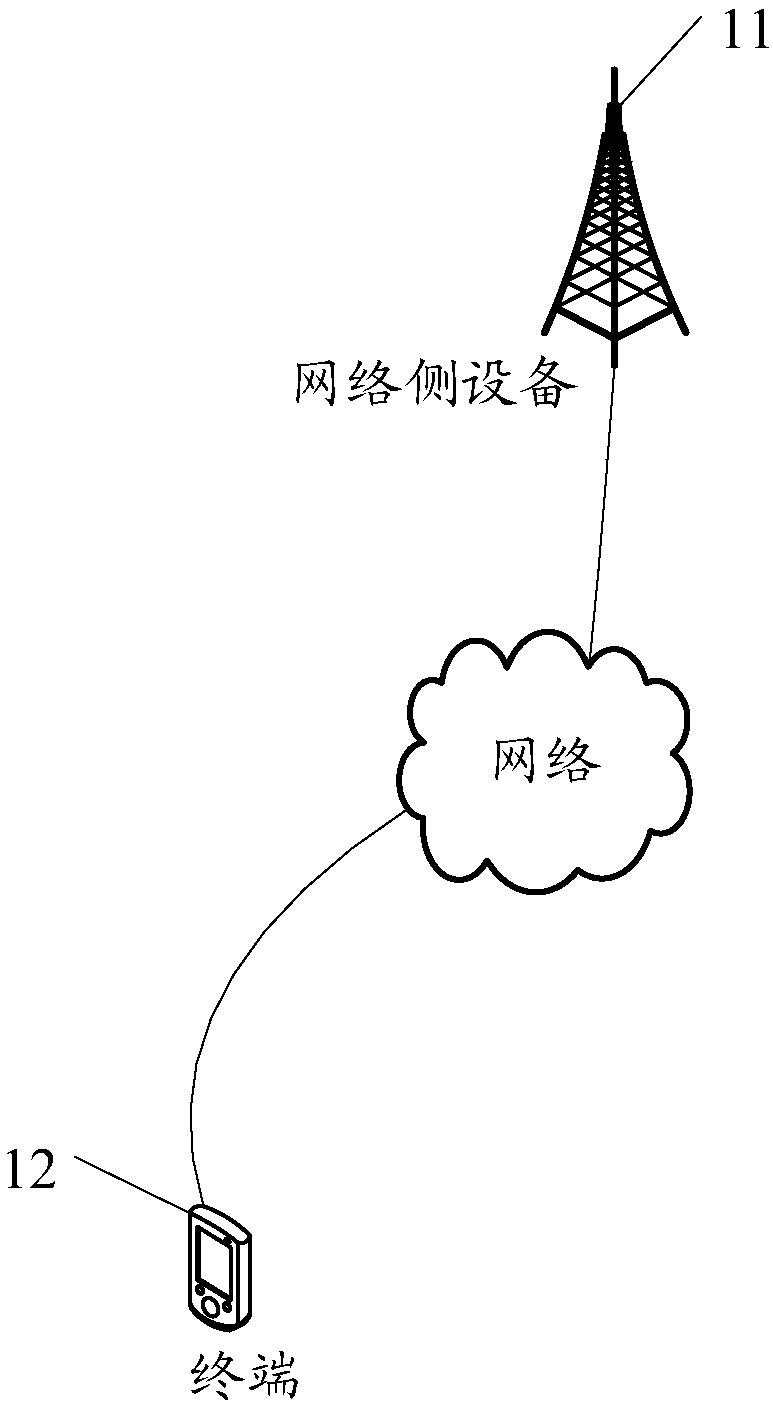
[0113] See figure 1 , figure 1 It is a schematic diagram of the network structure applied in the embodiment of the present invention; figure 1 As shown, a network side device 11 and a terminal 12 are included. The network side device 11 may be an evolved base station (eNB, evolved Node B) or other base station. It should be noted that the specific type of the network side device 11 is not limited in the embodiment of the present invention. The network side dev...


PUM


Abstract

The invention provides a data transmission control method, a network side device and a terminal, wherein the method comprises the following steps: the network side device maps code words on at least one data layer; the network side device maps the data layer on at least one quasi colocalization QCL group, wherein the QCL group is an antenna port group established according to a QCL relation amongvarious antenna ports; and the network side device performs data transmission based on the QCL group. With the method, the device and the terminal provided by the invention, data transmission of a multi-array antenna is realized.

Description

Technical field [0001] The present invention relates to the field of communication, in particular to a data transmission control method, network side equipment and terminal. Background technique [0002] In the current LTE system, during data transmission, the high-level transmission block is first mapped to at most two codewords, then the codewords are mapped to layers through the layer mapping module, and then the signal is mapped to the antenna port through layer-to-port mapping. The existing data transmission mechanism can support the transmission of up to 2 codewords and 8 data streams, but this method is only suitable for MIMO (Multiple-Input Multiple-Output) transmission of a single array. However, in a large-scale antenna system, multiple independent AAS (Adaptive Antenna System, adaptive antenna system) sub-array modules are likely to be used. The clock synchronization may be different, and the locations may be far apart, which cannot be used directly. Existing transmis...

Claims


Application Information

Patent Timeline
IPC IPC(8): H04B7/0456
CPCH04B7/0473H04B7/0697H04L1/0026H04L1/0031H04L5/0023H04L5/0044H04L5/0051H04L5/0091H04B7/0626H04L1/0003H04L5/10
Inventor 苏昕高秋彬李传军王蒙军塔玛拉卡·拉盖施陈润华李辉黄秋萍
Owner DATANG MOBILE COMM EQUIP CO LTD
Why Eureka
Try Eureka