Two-stage hydraulic cylinder with multi-layer core tube and crane

A technology of hydraulic cylinders and core tubes, which is applied in mechanical equipment, fluid pressure actuation devices, etc., can solve the problems that the levels cannot be controlled individually, and the mass and volume of multi-stage oil cylinders are large, so as to improve the performance of the boom and the stability of the whole machine , easy to place and optimize, and the effect of reducing the weight of the cylinder

Inactive Publication Date: 2018-07-20
XUZHOU HEAVY MASCH CO LTD
View PDF6 Cites 6 Cited by
  • Summary
  • Abstract
  • Description
  • Claims
  • Application Information

AI Technical Summary

Problems solved by technology

[0005] In order to solve the deficiencies in the prior art, the present invention provides a multi-layer core tube two-stage hydraulic cylinder, which solves the technical problems in the prior art that the mass and volume of the multi-stage cylinders are large and each stage cannot be controlled individually

Method used


Image

  • Two-stage hydraulic cylinder with multi-layer core tube and crane
  • Two-stage hydraulic cylinder with multi-layer core tube and crane

Examples


Embodiment 1

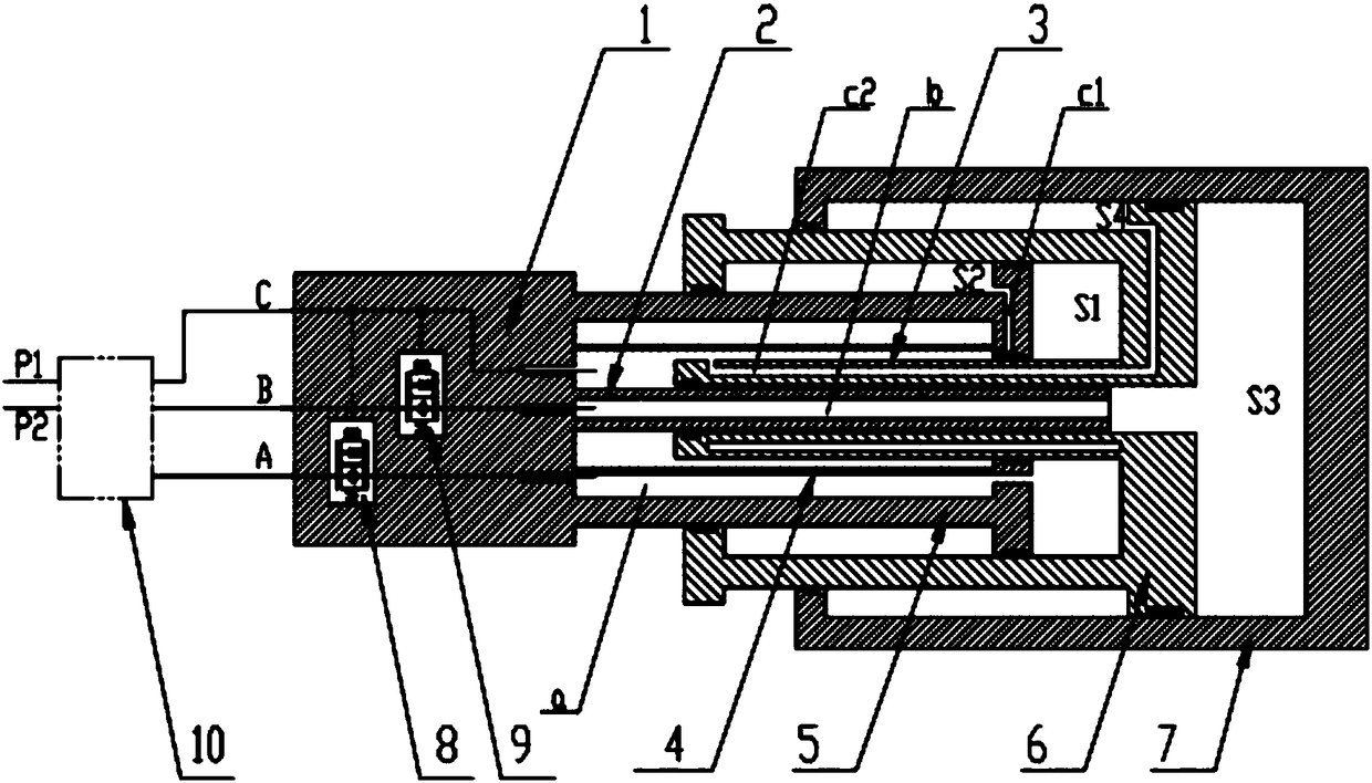
[0022] Such as figure 1 Shown: a two-stage hydraulic cylinder with a multi-layer core tube, including a piston rod head (1), an inner telescopic core tube (2), a casing (4), a piston rod assembly (5), a first-stage cylinder barrel (6 ) and the second-stage cylinder (7), the piston rod head 1 has three working oil ports A, B, and C, and the first balance valve 8 and the second balance valve 9 are arranged inside, and the two balance valves include Two work ports and one control port. The piston rod head 1 is connected to the piston rod assembly 5, the sleeve 4 and the inner telescopic core tube 2, the first-stage cylinder 6 is built into the second-stage cylinder 7, and the first-stage cylinder 6 is connected (built-in) to the piston rod The outer cavity of the assembly 5 and the inner cavity connected to the inner telescopic core tube 2, the first stage cylinder 6 is also provided with the outer telescopic core tube 3, and the second stage cylinder 7 is in the outermost layer...

Embodiment 2

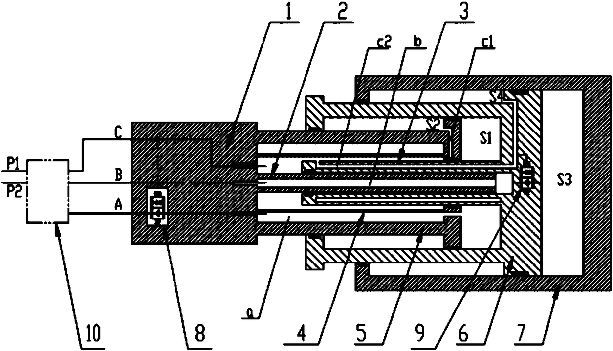
[0045] Such as figure 2 As shown, the difference between this embodiment and Embodiment 1 is that the second balance valve 9 is built inside the first-stage cylinder 6, and the two working oil ports are connected to the inner cavity of the first-stage cylinder 6 and the second-stage cylinder respectively. The rodless chamber S3 of the second-stage cylinder, the control oil port connection channel 4 C2 (when there is no pressure at the control oil port, the inner cavity of the first-stage cylinder 6 is unidirectionally connected to the rodless chamber S3 of the second-stage cylinder), specifically The process is basically the same as that in Embodiment 1, and will not be repeated here.


PUM


Abstract

The invention discloses two-stage hydraulic cylinder with multi-layer core tubes and a crane, and belongs to the technical field of engineering machinery. The two-stage hydraulic cylinder with the multi-layer core tubes comprises a piston rod head, an inner telescopic core tube, a sleeve, a piston rod assembly, a first-stage cylinder barrel and a second-stage cylinder barrel, wherein one end of the inner telescopic core tube, one end of the sleeve and one end of the piston rod assembly are connected to the piston rod head; the first-stage cylinder barrel is provided with an outer telescopic core tube, multiple working oil ports are formed in the piston rod head, the first-stage cylinder barrel is arranged in the second-stage cylinder barrel, and the first-stage cylinder barrel is providedwith an outer cavity connected to the sleeve and the piston rod assembly and an inner cavity connected to the inner telescopic core tube; and the working oil ports can independently control extensionand retraction of the first-stage cylinder barrel and the second-stage cylinder barrel. According to the two-stage hydraulic cylinder with multi-layer core tubes and the crane, all stages of the cylinders can be independently controlled and are not limited in sequence, various working conditions of the device are met, the weight of an oil cylinder is greatly reduced, the performance of a suspension arm and the stability of the whole machine are improved, the arrangement space is saved, and arrangement and optimization of a rope arrangement mechanism are facilitated.

Description

technical field [0001] The invention relates to the field of engineering machinery, in particular to a two-stage hydraulic cylinder with a multi-layer core tube and a crane. Background technique [0002] At present, the boom telescopic mechanism of small-tonnage cranes (five-section boom and below) at home and abroad generally adopts a double-cylinder plus rope row structure. advantages, but this structure also has the following disadvantages: 1. The weight of the double hydraulic cylinders is relatively large, which will have a certain impact on the force of the boom and hydraulic cylinders when the operation is carried out in the working conditions above the middle and long arms; 2. The arrangement of double hydraulic cylinders takes up a lot of space, affects the section of the boom, and has certain restrictions on the arrangement of the rope row mechanism; 3. The cost of double hydraulic cylinders is relatively high. [0003] Theoretically, multi-stage hydraulic cylinde...

Claims


Application Information

Patent Timeline
IPC IPC(8): F15B15/16F15B15/20
CPCF15B15/16F15B15/1423F15B15/1457F15B2215/30
Inventor 郭志臣马善华张付义李增彬
Owner XUZHOU HEAVY MASCH CO LTD
Why Eureka
Try Eureka