
Hydraulic combination system for dumper

A combined system and dump truck technology, applied in fluid pressure actuating devices, vehicles with tilt bearing motion, servo motors, etc., can solve the problems of high starting pressure of the working system, poor system stability, heavy cylinder weight, etc., to reduce steel The effect of usage, life extension, and cylinder weight reduction

Inactive Publication Date: 2014-10-15
NINGBO JIANGDONG CHENGCHUANG IND PROD DESIGN CO LTD +1
View PDF8 Cites 0 Cited by
  • Summary
  • Abstract
  • Description
  • Claims
  • Application Information

AI Technical Summary

Problems solved by technology

[0006] In the oil cylinder described in the above-mentioned patent, the cylinder shell only plays a supporting role, and the cross-sectional diameter of the cylinder shell itself is relatively large, and the weight of the shell itself is very heavy. This design causes the weight of the oil cylinder itself to be relatively large. It cannot be extended by itself, and the size of the oil cylinder is relatively large. For the entire dump truck hydraulic combination system, the starting pressure of the working system is relatively high, and the system stability is poor.

Method used


Image

  • Hydraulic combination system for dumper
  • Hydraulic combination system for dumper
  • Hydraulic combination system for dumper

Examples


Embodiment 1

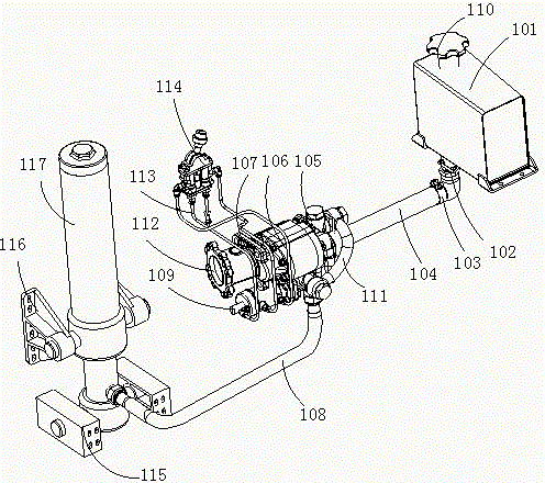
[0043] see figure 1 As shown, it is a structural schematic diagram of a dump truck hydraulic combination system according to an embodiment of the present invention. The hydraulic combination system in the present invention includes a fuel tank 101, a pump valve combination assembly 105, and an oil cylinder combination 117. The pump valve combination assembly 105 connects the fuel tank 101 The low-pressure hydraulic oil in the pump is converted into high-pressure hydraulic oil and transmitted to the oil cylinder assembly 117 through the high-pressure oil pipe 108. In the present invention, the hydraulic assembly system is installed on the dump truck, and the oil cylinder assembly 117 is combined with the tipping bucket of the dump truck to lift Raise or lower the bucket. In this embodiment, the pump-valve assembly 105 is used to convert the low-pressure hydraulic oil. Ordinary hydraulic oil pumps can also be used, and connected to the oil tank and hydraulic cylinder through the...

Embodiment 2

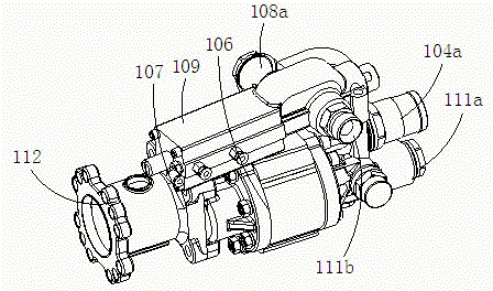
[0075] see Figure 8 As shown in FIG. 2 , it is a structural schematic diagram of the dump truck hydraulic combination system in Embodiment 2 of the present invention. The difference from the above-mentioned embodiments is that the working pressure of the pump-valve combination assembly is high, and two inlet and outlet oil pipes 104a are arranged on the pump-valve assembly. A low-pressure oil pipe 104 is connected to the oil inlet and outlet 101a, and a valve oil outlet pipe is provided on the valve 109, which is connected with the oil outlet pipe 108 to provide hydraulic oil to the actuator; correspondingly, a valve return valve is also provided inside the valve body. Oil pipe, the oil return pipe communicates with the inlet and outlet oil pipe 104a of the valve and the pump. When the valve body returns oil, the hydraulic oil flows into the oil inlet and outlet pipe 104a through the valve oil return pipe.

[0076] The valve 109 is provided with a valve oil outlet pipe 108a,...


PUM


Abstract

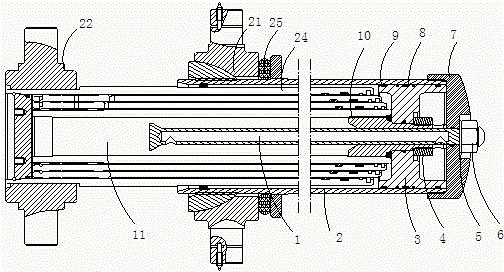
The invention relates to a hydraulic combination system for a dumper. The hydraulic combination system for the dumper comprises a fuel tank, a pump, an oil cylinder assembly and a power takeoff. The power takeoff is fixedly connected with the pump, the oil cylinder assembly comprises a multilevel telescopic cylinder which is connected with a piston assembly, and the multilevel telescopic cylinder and the piston assembly are arranged on two sides in a piston cylinder barrel and contact with each other; the piston assembly comprises a telescopic part and a piston, the telescopic part is arranged in a cavity of the multilevel telescopic cylinder, and the piston is fixed onto the telescopic part and fits the piston cylinder barrel; the telescopic part is fixed with an end cover at the end of the piston cylinder barrel. The hydraulic combination system for the dumper has the advantages that by combination of the multilevel telescopic cylinder and the piston assembly, an oil cylinder supporting jacket becomes a piston cylinder body; by the aid of a multilevel cylinder barrel serving as a piston rod, the oil cylinder can be effectively lightened in weight and reduced in size, and accordingly pressure on the hydraulic combination system for the dumper can be alleviated, and the service life of the hydraulic system is prolonged.

Description

[0001] technical field [0002] The invention relates to the field of dump trucks, in particular to a dump truck hydraulic combination system with telescopic cylinders. [0003] Background technique [0004] The dump truck hydraulic combination system in the prior art generally includes a fuel tank, a pump and a hydraulic cylinder, and the fuel tank and the pump provide power to the hydraulic cylinder, so as to control the extra actions of the dump truck. In the field of dump trucks, multi-stage telescopic cylinders are generally used, and multi-stage telescopic cylinders are set in the cylinder shell. When working, the shell and the end cover only play a supporting role, and the multi-stage telescopic cylinders inside the shell are in the hydraulic oil. Under the action of the telescopic oil cylinder, it stretches out successively according to the size of the cross-sectional area of ​​the telescopic cylinder. [0005] For example, the Chinese patent "Guide Slot Traverse C...

Claims


Application Information

Patent Timeline
IPC IPC(8): F15B11/028F15B15/24B60P1/16
Inventor 涂雪龙
Owner NINGBO JIANGDONG CHENGCHUANG IND PROD DESIGN CO LTD
Learn More