Pseudo code capturing method and device

A pseudo-code and pseudo-code sequence technology, applied in electrical components, transmission systems, etc., can solve the problems of large system resource consumption, failure to use pseudo-code to capture, and inability to achieve capture, achieving low false alarm rate and strong anti-interference ability , the effect of short capture time

Active Publication Date: 2018-07-27
武汉船舶通信研究所
View PDF9 Cites 4 Cited by
  • Summary
  • Abstract
  • Description
  • Claims
  • Application Information

AI Technical Summary

Problems solved by technology

[0006] Using the sliding correlation method for pseudo code capture, on the one hand, the system resource consumption is large, and the capture time is long; ) output has no correlation peak, and capture cannot be realized, and cannot be used for pseudocode capture of direct spread communication systems working under very low signal-to-noise ratio conditions

Method used


Image

  • Pseudo code capturing method and device
  • Pseudo code capturing method and device
  • Pseudo code capturing method and device

Examples


Embodiment Construction

[0053] In order to make the object, technical solution and advantages of the present invention clearer, the implementation manner of the present invention will be further described in detail below in conjunction with the accompanying drawings.

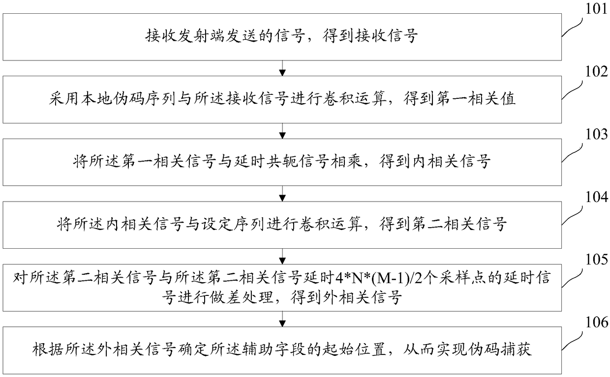
[0054] figure 1 It is a flowchart of a pseudocode capture method provided by an embodiment of the present invention, see figure 1 , the method includes:

[0055] Step 101: Receive a signal sent by a transmitting end to obtain a received signal, and the received signal is used to transmit an information frame.

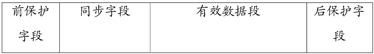
[0056] figure 2 is a schematic diagram of the frame format provided by the embodiment of the present invention, see figure 2 , the information frame includes a pre-protection field, a synchronization field, valid data and a post-protection field. image 3 is a schematic structural diagram of the synchronization field provided by the embodiment of the present invention, see image 3 , the synchronization field includes an au...


PUM


Abstract

The invention discloses a pseudo code capturing method and device, and belongs to the technical field of communication. The pseudo code capturing method comprises the steps of receiving a signal sentby a transmitting end to obtain a received signal; performing convolution operation by adopting a local pseudo code sequence and the received signal so as to obtain a first correlation signal, whereinthe local pseudo code sequence is the pseudo code sequence same as the pseudo code sequence in an auxiliary field; multiplying the first correlation signal with a delayed conjugation signal to obtainintercorrelation signal, and the delayed conjugation signal is a conjugation signal of delay signal of the first correlation signal which delays for 4*M sampling points; performing convolution operation on the intercorrelation signal and a set sequence to obtain a second correlation signal, wherein the set sequence comprises M-1 bits with the value as 1, and 4*N-1 bits with the value as zero exist between each two adjacent bits with the value as 1; performing differencing processing on the second correlation signal and the delay signal of the second correlation signal which delays for 4*N*(M-1)/2 sampling points to obtain an external correlation signal; and determining a start position of the auxiliary field based on the external correlation signal so as to accordingly realize pseudo codecapturing.

Description

technical field [0001] The invention relates to the field of communication technology, in particular to a method and device for capturing pseudocodes. Background technique [0002] Direct Sequence Spread Spectrum (Direct Sequence Spread Spectrum) working mode (referred to as direct spread mode) is to use a high-rate spreading sequence to spread the spectrum of the signal at the transmitting end, and use the same spreading code sequence to despread at the receiving end. The unfolded spread spectrum signal is restored to the original signal. Direct spread communication system is widely used in military microwave high-speed data transmission system due to its strong anti-interference, anti-noise, anti-multipath fading ability, good confidentiality, strong multiple access capability and high-precision measurement. . [0003] Spread spectrum pseudo code synchronization is the basis of direct spread communication system. Only when the pseudo code synchronization is completed, so...

Claims


Application Information

Patent Timeline
Patent Type & Authority Applications(China)
IPC IPC(8): H04B1/7077H04B1/7075
Inventor 李朝阳朱振宇付兴胡娟
Owner 武汉船舶通信研究所
Why Eureka
Try Eureka