Vibration type glue hanging device for auto spare parts

A technology for auto parts and equipment, which is applied in coatings and devices for coating liquid on the surface, etc. It can solve the problems of the quality of the glue coating of interior parts and other problems, and achieve the effect of reducing the blind area of ​​glue coating

Active Publication Date: 2018-07-31
ANHUI TECHN COLLEGE OF MECHANICAL & ELECTRICAL ENG
View PDF5 Cites 0 Cited by
  • Summary
  • Abstract
  • Description
  • Claims
  • Application Information

AI Technical Summary

Problems solved by technology

[0002] In the field of auto parts, various types of automotive interior parts need to be glued or electroplated. In the glue coating operation, it is necessary to send the generally square or circular interior parts into the glue pool For hanging glue, the current common method is to hang the interior parts through a special glue hanger, and then send the glue hanger into the glue pool, but the hanging operation of the interior parts on the glue hanger often requires the use of chucks or It is realized by other clamping and fixing devices, which will inevitably cause the blind area of ​​gluing due to the obstruction of the clamping device during the gluing operation of the interior parts, which will affect the quality of the gluing of the interior parts. Need a kind of novel glue-hanging equipment to solve the above problems

Method used


Image

  • Vibration type glue hanging device for auto spare parts
  • Vibration type glue hanging device for auto spare parts
  • Vibration type glue hanging device for auto spare parts

Examples


Embodiment Construction

[0016] The following will clearly and completely describe the technical solutions in the embodiments of the present invention with reference to the accompanying drawings in the embodiments of the present invention. Obviously, the described embodiments are only some, not all, embodiments of the present invention. Based on the embodiments of the present invention, all other embodiments obtained by persons of ordinary skill in the art without making creative efforts belong to the protection scope of the present invention.

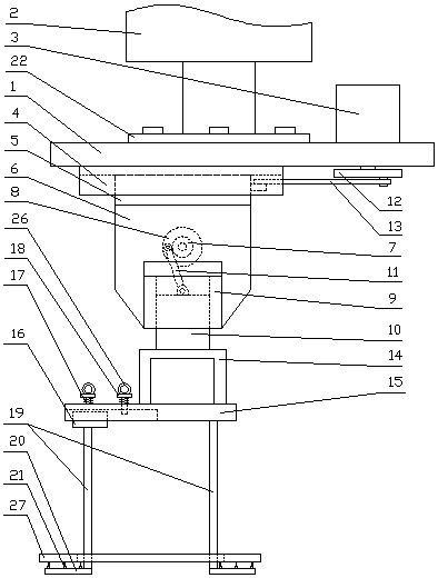
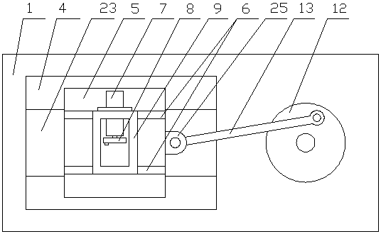
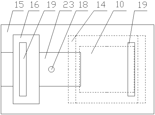
[0017] see Figure 1-5 , the present invention provides a technical solution: an oscillating glue-hanging equipment for auto parts, including a roof frame 1, the top of the roof frame 1 is connected to a lifting cylinder 2, and a Traversing motor 3, guide frame 4 is installed on the bottom of described roof frame 1, and traverse frame 5 is slidably fitted on described guide frame 4, and the bottom of described traverse frame 5 is welded with several vertical p...


PUM


Abstract

The invention discloses a vibration type glue hanging device for auto spare parts. The vibration type glue hanging device for the auto spare parts comprises a top plate frame, wherein a transverse motor is arranged at one side position of the top part of the top plate frame; a guiding frame is arranged on the bottom part of the top plate frame; a transverse frame slidably fits onto the guiding frame; multiple standing plates are welded to the bottom part of the transverse frame; a vertical moving motor is detachably connected onto the standing plates and is matched with a vertical moving eccentric wheel; the bottom parts of the standing plates are welded with a square sleeve; a square column is slidably matched into the square sleeve; the transverse motor is matched with the vertical moving eccentric wheel; the bottom part of the square column is connected with a bottom plate frame; an adjusting frame is slidably matched to one side of the bottom part of the bottom plate frame; supportplate legs are welded to the bottom part of the adjusting frame and at the position of one end of the bottom part of the bottom plate frame; and support plate frames are welded to the bottom parts ofthe support plate legs. The vibration type glue hanging device for the auto spare parts is simple to operate, can be powered on for work so as to be labor-saving and fast, and is high in safety, andthe blind area existed during the glue hanging work of the auto spare parts can be reduced.

Description

technical field [0001] The invention relates to the field of auto parts production equipment, in particular to an oscillating type glue hanging equipment for auto parts. Background technique [0002] In the field of auto parts, various types of automotive interior parts need to be glued or electroplated. In the glue coating operation, it is necessary to send the generally square or circular interior parts into the glue pool For hanging glue, the current common method is to hang the interior parts through a special glue hanger, and then send the glue hanger into the glue pool, but the hanging operation of the interior parts on the glue hanger often requires the use of chucks or It is realized by other clamping and fixing devices, which will inevitably cause the blind area of ​​gluing due to the obstruction of the clamping device during the gluing operation of the interior parts, which will affect the quality of the gluing of the interior parts. Need a kind of novel gluing eq...

Claims


Application Information

Patent Timeline
IPC IPC(8): B05C3/10B05C13/02
CPCB05C3/10B05C13/02
Inventor 邹家鹏陶仁元孙俊陈高朋
Owner ANHUI TECHN COLLEGE OF MECHANICAL & ELECTRICAL ENG
Why Eureka
Try Eureka