Head-Mounted Viewable Device and Eye-Tracking System for Use in Head-Mounted Viewable Device

a head-mounted viewable device and eye-tracking technology, which is applied in the field of virtual reality, can solve the problems of limiting the application of the head-mounted viewable device in the real industry, affecting the virtual visual experience of users, and limiting the scope of the head-mounted viewable device. the effect of improving the overall performance of the head-mounted viewable device and simplifying the optical system of the eye-tracking

Active Publication Date: 2022-10-06
YUYAO SUNNY OPTICAL INTELLIGENCE TECH CO LTD
View PDF10 Cites 0 Cited by
  • Summary
  • Abstract
  • Description
  • Claims
  • Application Information

AI Technical Summary

Benefits of technology

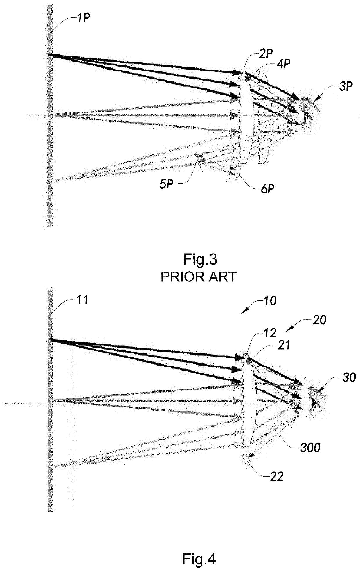
[0007]Another advantage of the invention is to provide a head-mounted viewable device and eye-tracking system thereof, wherein the optical path of the eye-tracking system does not pass through the VR optical lens, and thus the VR optical lens merely needs to optically process the images to be displayed and projected from a display, without having to take consideration of the interference of the eye tracking system. In other words, the optical parameters of the VR lens are relatively uniform so as to facilitate an optical design and manufacturing of the VR optical lens.
[0008]Another advantage of the invention is to provide a head-mounted viewable device and eye-tracking system thereof, wherein the optical path of the eye-tracking system does not pass through the VR optical lens. In other words, the VR optical lens and the eye-tracking system are optically independent with each other, thereby improving the stability of the overall performances of the head-mounted viewable device.
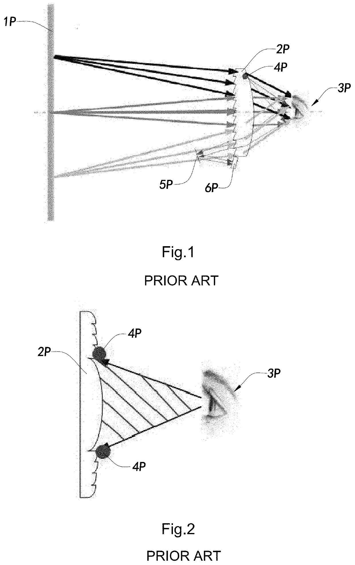
[0009]Another advantage of the invention is to provide a head-mounted viewable device and eye-tracking system thereof, wherein a detection light intended for eye-tracking, after being diffused and reflected by the user's eye, is directly perceived by a receiving module of the eye-tracking system, so that compared with the conventional eye-tracking system of the head-mounted viewable device, a reflector for reflecting the detection light can be eliminated, thereby simplifying the optical system of the eye-tracking system and reducing the costs thereof.
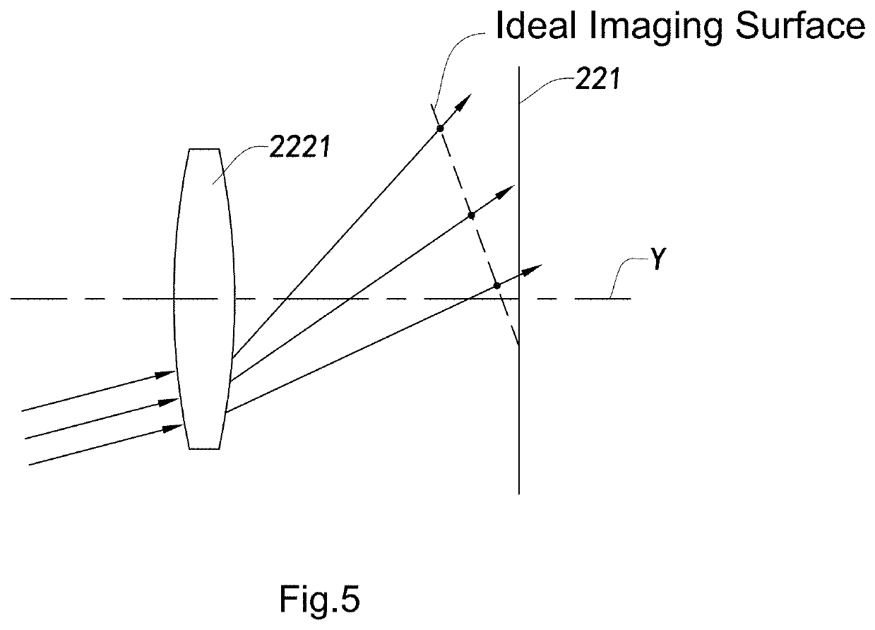
[0010]Another advantage of the invention is to provide a head-mounted viewable device and eye-tracking system thereof, wherein a plane defined by a photosensitive element of the receiving module and a plane defined by an optical lens thereof are at a predetermined angle. In other words, the plane defined by the photosensitive element is inclined with the plane defined by the optical lens, in such an “inclined imaging” manner to simplify the design of the optical system of the receiving module so as to improve the imaging quality of the receiving module.
[0011]Another advantage of the invention is to provide a head-mounted viewable device and eye-tracking system thereof, wherein the relative illumination of the images captured by the receiving module is compensated in such an “inclined imaging” manner.
[0012]Another advantage of the invention is to provide a head-mounted viewable device and eye-tracking system thereof, wherein the light source for generating and projecting the detection light in the eye-tracking system of the present invention has a relatively smaller size, so that the interference of the light source to the observation of the user' eye can be substantially minimized. In other words, the light source with a relatively smaller size is able to reduce a blind area of the user's eye.

Problems solved by technology

However, there are still many technical difficulties in the implementation of the head-mounted viewable device, especially the design of the optical system thereof, which seriously affect user's virtual visual experience and limit a wider application of the head-mounted viewable device in real industry.

Method used


Image

  • Head-Mounted Viewable Device and Eye-Tracking System for Use in Head-Mounted Viewable Device
  • Head-Mounted Viewable Device and Eye-Tracking System for Use in Head-Mounted Viewable Device
  • Head-Mounted Viewable Device and Eye-Tracking System for Use in Head-Mounted Viewable Device

Examples


Embodiment Construction

[0058]The following description is disclosed to enable any person skilled in the art to make and use the present invention. Preferred embodiments are provided in the following description only as examples and modifications will be apparent to those skilled in the art. The general principles defined in the following description would be applied to other embodiments, alternatives, modifications, equivalents, and applications without departing from the spirit and scope of the present invention.

[0059]Those skilled in the art should understand that, in the disclosure of the present invention, terminologies of “longitudinal,”“lateral,”“upper,”“front,”“back,”“left,”“right,”“perpendicular,”“horizontal,”“top,”“bottom,”“inner,”“outer,” and etc. just indicate relations of direction or position are based on the relations of direction or position shown in the appended drawings, which is only to facilitate descriptions of the present invention and to simplify the descriptions, rather than to indi...


PUM


Abstract

A head-mounted viewable device which includes a display configured to display and project a virtual scene image to a user's eye, a VR optical lens configured to construct an optical path between the display and the user's eye for allowing a virtual scene image being observed by the user's eye, and, an eye-tracking system configured to detect a sight direction of the user's eye and adjust a display position of the virtual scene image based on the detected sight direction. The eye-tracking system includes at least one light source configured to project the detection light and a receiving module configured to receive the reflected detection light reflected to determine the sight direction of the user's eye. The receiving module is positioned at a side of the VR optical lens and arranged to face towards the user's eye such that the detection light reflected by the user's eye is directly received by the receiving module.

Description

CROSS REFERENCE OF RELATED APPLICATION[0001]This application is a Continuation application that claims the benefit of priority under 35 U.S.C. § 120 to a non-provisional application, application Ser. No. 17 / 266,978, filed Feb. 8, 2021, which is a U.S. National Stage under 35 U.S.C. 371 of the International Application Number PCT / CN2019 / 084943, filed Apr. 29, 2019, which claims priority under 35 U.S.C. 119(a-d) to Chinese application number CN201810945241.1, filed Aug. 20, 2018, which are incorporated herewith by reference in their entirety.BACKGROUND OF THE PRESENT INVENTIONField of Invention[0002]The present invention relates to the field of virtual reality, and more particularly to a head-mounted viewable device and eye-tracking system thereof.Description of Related Arts[0003]In recent years, virtual reality (VR) and augmented reality (AR) have created a special visual experience for human beings. VR (Virtual Reality) is an interactive visual experience in a simulated environment ...

Claims


Application Information

Patent Timeline
Patent Type & Authority Applications(United States)
IPC IPC(8): H04N13/344H04N13/383G02B3/04G02B25/00G02B27/00G06F3/01
CPCH04N13/344H04N13/383G02B3/04G02B25/001G02B27/0093G06F3/013G06F3/011
Inventor ZHANG, KOUWENGUO, MEISHANSONG, LITONGTANG, WEIXIE, JIAN
Owner YUYAO SUNNY OPTICAL INTELLIGENCE TECH CO LTD
Why Eureka
Try Eureka