Bidirectional current detection circuit
A detection circuit, bidirectional current technology, applied in the direction of adjusting electrical variables, control/regulation systems, instruments, etc., can solve the problems of reducing sampling accuracy, increasing circuit cost and complexity, and limited application range
Active Publication Date: 2018-07-31
SUZHOU REGU TECH INC
View PDF3 Cites 4 Cited by
- Summary
- Abstract
- Description
- Claims
- Application Information
AI Technical Summary
Problems solved by technology
However, most of these current sense amplifier control chips generally do not have the ability to accept positive and negative polarity voltages. Therefore, an additional circuit is required to level shift the voltage, which increases the cost and complexity of the circuit. , on the other hand reduces the sampling accuracy
However, some current sense amplifier control chips can detect bidirectional current flow, but the application range is limited to the current flow between positive voltages.
Method used
View moreImage
Smart ImageViewing Examples


Examples
Embodiment 1
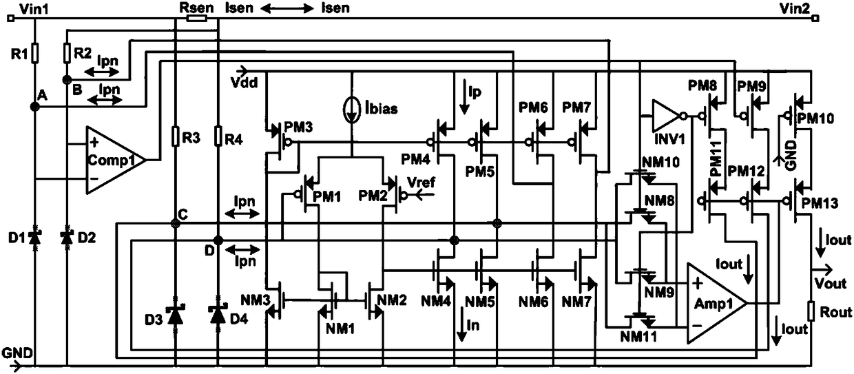
[0033] A bidirectional current sensing circuit such as figure 2 As shown, it includes a first amplifying circuit, a second amplifying circuit, a first current mirror, a second current mirror, a third current mirror, a first switching circuit, a second switching circuit, a comparator Comp1, an amplifier Amp1, and an inverter INV1 , resistance R1 ~ R4;
Login to View More PUM
 Abstract
The invention discloses a bidirectional current detection circuit. The bidirectional current detection circuit comprises a first amplifying circuit, a second amplifying circuit, a first current mirror, a second current mirror, a third current mirror, a first switch circuit, a second switch circuit, a comparator Comp1, an amplifier Amp1, an inverter INV1 and resistors R1-R4; a resistor Rsen is arranged between a test access end Vin1 and a test access end Vin2; the test access end Vin1 is connected with an inversing input end of the comparator Comp1 through the resistor R1, and the test access end Vin2 is connected to a positive input end of the comparator Comp1 through the resistor R2; the output end of the comparator Comp1 is connected with the second switch circuit; the second switch circuit is used for controlling on and off of the first switch circuit; the bidirectional current detection circuit can detect the current size and the flow direction of current simultaneously.
Description
technical field [0001] The invention relates to the technical field of current detection, in particular to a bidirectional current detection circuit. Background technique [0002] Current sense amplifiers are widely used in welding equipment, computers, mobile phones, telecommunication equipment, automotive, power management, battery chargers, etc. By monitoring the magnitude and direction of current flow, motor torque, solenoid force, LED density, solar cell light exposure, battery charge, etc. can be best monitored. Therefore, a circuit is needed that can accurately measure the current and convert the current to a voltage, so that the voltage can be amplified, regulated, and measured with existing voltage devices (amplifiers, comparators, ADCs, etc.). In these applications, the amplifier in the current sense circuit is used to extract the small differential voltage generated by the current through the small sense resistor from the high common mode voltage, such as figure...
Claims
Login to View More Application Information
Patent Timeline
 IPC IPC(8): G05F3/26
CPCG05F3/262
Inventor 黄胜明郭天冯多力黄鑫
Owner SUZHOU REGU TECH INC

PatSnap Eureka turns technology decisions into work you can execute. Powered by our Innovation Knowledge Graph, it runs expert workflows across engineering, life sciences, materials and intellectual property. Get your review-ready output in minutes.


