Compressed air braking system for a vehicle and method for controlling such a compressed air braking system

A technology of braking system and compressed air, applied in the direction of braking action starting device, brake, braking component, etc., can solve the problem that the connecting device is not suitable for switching back and forth

Active Publication Date: 2021-09-24
ZF CV SYST EURO BV
View PDF4 Cites 0 Cited by
  • Summary
  • Abstract
  • Description
  • Claims
  • Application Information

AI Technical Summary

Problems solved by technology

[0011] However, it can be pointed out that this method may lead to unfavorable switching back and forth of the switching device, wherein during this switching process, there will be sudden changes in the braking performance, because, for example, in the driver simulated from it When the brake pressure is applied to the activation device, when the driver's braking operation is switched to the driver's auxiliary braking operation, first of all the high system pressure is applied to the activation device very suddenly and only then is activated by the ABS. The shut-off valve decreases in a clocked manner

Method used


Image

  • Compressed air braking system for a vehicle and method for controlling such a compressed air braking system
  • Compressed air braking system for a vehicle and method for controlling such a compressed air braking system

Examples


Embodiment Construction

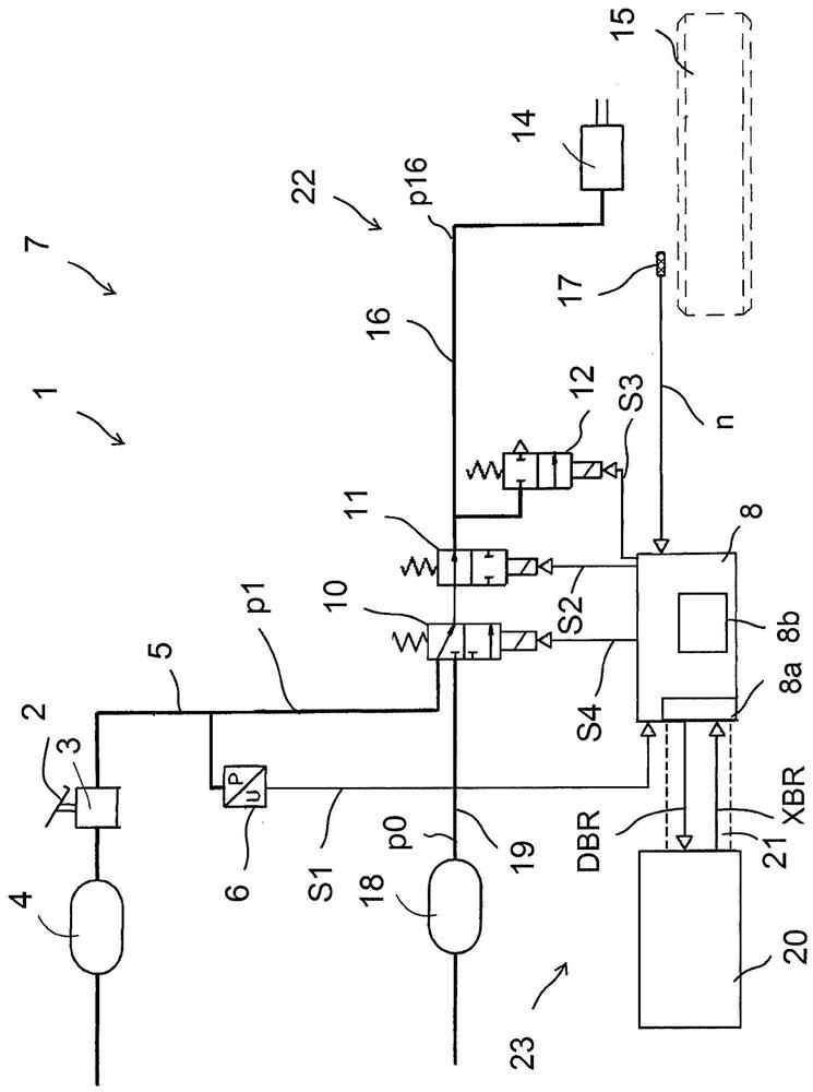
[0026] Compressed air brake systems for commercial vehicles1 in figure 1is shown for the brake circuit. The driver actuates the brake valve 3 via the brake pedal 2 , so that compressed air from the first compressed air reserve reservoir 4 is supplied to the brake pressure control line 5 . A simulated driver brake pressure p1 is thus applied to the brake pressure control line 5 via the brake valve 3 as a function of the actuation of the brake pedal 2 . The pressure sensor 6 measures the simulated driver's brake pressure p1 and outputs a brake pressure measurement signal S1 to the ABS control unit 8 . The simulated driver brake pressure p1 is then supplied to the switching valve arrangement 10 , which is designed here as a 3 / 2 solenoid directional valve or switching valve 10 . In its basic position, the switch-on valve 10 is in its driver's braking position, in which the switch-on valve leads the brake pressure control line 5 to at least one brake circuit, that is to say via ...


PUM


Abstract

The invention relates to a method for controlling a compressed air brake system (1) of a vehicle, which has the following steps: In the case of driver braking (FB) by actuating the brake pedal, via brake pressure control The circuit, switch-on device set into the driver's braking position (S4=0) outputs the simulated driver's brake pressure to the brake circuit (St4) with at least one ABS shut-off valve device, the brake circuit and the wheel brakes , in the presence of an external brake request signal from the driver assistance system without the driver braking at the same time, the switch-on device is switched into the functional position, the system pressure is passed to the ABS shut-off valve device and controlled by the actuation ABS shut-off valve arrangement for regulating the simulated brake pressure to at least one brake line (St5) of a brake circuit with at least one wheel brake, characterized in that when the driver's brake is present and an external brake request signal is present In the case of measuring the driver's brake pressure and obtaining the driver's brake pressure value, the driver's brake pressure value and the external brake pressure value contained in the external request signal are added or superimposed into a combined brake pressure value, and the switch-on device is switched to the functional position, and the combined brake pressure value (St6) is regulated from the system pressure by actuating the ABS shut-off valve device.

Description

technical field [0001] The invention relates to a compressed air braking system for a vehicle and a method for controlling such a compressed air braking system. Background technique [0002] Depending on the regulation of the brake pressure achieved by the driver when the brake pedal is actuated during the driver's braking operation, compressed air brake systems for vehicles can be divided into those with analogue functions, also known as ABS systems. Compressed air brake systems for brake pressure lines and electronic brake systems also known as EBS systems. [0003] In a simulated braking system or ABS braking system, when the brake pedal is actuated, a simulated compressed air value is provided by the coupled brake valve to the brake pressure control circuit, which is then (Possibly via further valve devices, such as axle load distributors and valve devices for switching on further functions) to one or more brake circuits. In addition, an ABS control device for regulati...

Claims


Application Information

Patent Timeline
Patent Type & Authority Patents(China)
IPC IPC(8): B60T8/171
CPCB60T7/042B60T7/22B60T13/662B60T13/683B60T15/024B60T2201/024B60T8/171B60T15/027
Inventor 丹尼尔·汉斯利克斯特凡·卡伦巴赫亚历山大·文德兰特
Owner ZF CV SYST EURO BV
Why Eureka
Try Eureka