Pipe bending device

A technology of a pipe bending device and a column is applied in the field of pipe bending devices, which can solve the problems of reduced processing efficiency, and achieve the effects of improving efficiency, fast transfer speed, and saving labor and labor time.

Active Publication Date: 2018-08-03
宁波鑫神泽汽车零部件有限公司
View PDF9 Cites 1 Cited by
  • Summary
  • Abstract
  • Description
  • Claims
  • Application Information

AI Technical Summary

Problems solved by technology

[0006] The purpose of the present invention is to provide a pipe bending device to solve the problem that the steel pipe needs to be manually loosened and transferred after the pipe bending is completed, thereby reducing the processing efficiency

Method used


Image

  • Pipe bending device
  • Pipe bending device
  • Pipe bending device

Examples


Embodiment 1

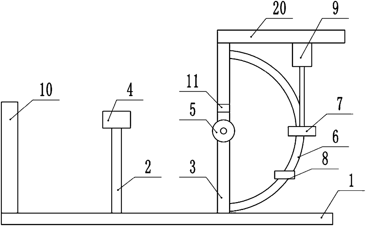
[0025] like figure 1 As shown, a pipe bending device includes a base 1, a slide rail is installed on the base 1, a push plate 10 with rollers is installed in the slide rail, and the push plate 10 slides in the slide rail through the rollers and can maintain a vertical state; The middle part of the base 1 is equipped with a support column 2 through bolts, and the upper end of the support column 2 is equipped with a jacket 4 through bolts, and a horizontal transverse groove is opened on the jacket 4; The middle part is equipped with a supporting roller 5, the lower end surface of the transverse groove is on the same horizontal line as the upper end surface of the supporting roller 5, and the middle part of the supporting roller 5 is provided with an annular groove, and an air bag is installed on the inner wall of the groove; the column 3 is also welded There is a scale ring 6, the scale is printed on the dial plate, and a scale groove is provided on the dial plate, and a positio...

Embodiment 2

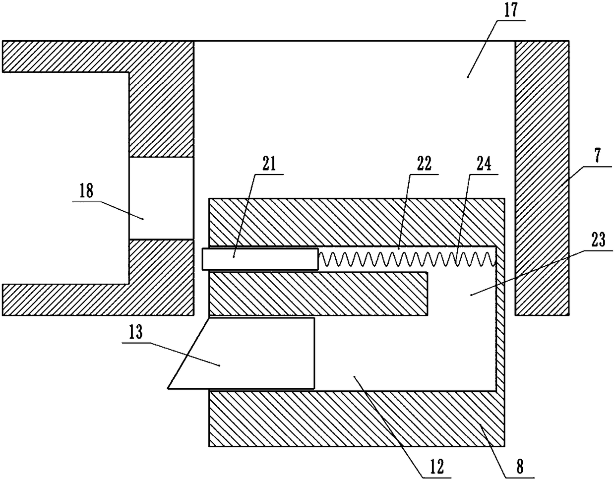
[0028] like image 3As shown, the difference from the bending device in Embodiment 1 is that the push mechanism includes a top block 21 and a horizontal sliding hole 22, the top block 21 slides and is sealed in the sliding hole 22, and the sliding hole 22 is located at the positioning block 8 Above, there is a channel 23 connected between the sliding hole 22 and the cavity structure 12, and a second spring 24 is connected between the inner wall of the channel 23 and the top block 21; When it is flush with the left end face of the positioning block 8, the telescopic block 13 abuts against the limit part; when the ferrule 7 pushes the telescopic block 13 to move into the cavity structure 12, the telescopic block 13 pushes the air in the cavity structure 12 to move, Air movement pushes the top block 21 through the through hole 18 to push the steel pipe away from the ferrule 7 .


PUM


Abstract

The invention belongs to the technical field of pipe bending equipment, and particularly discloses a pipe bending device. The pipe bending device comprises a base, wherein a supporting column and a stand column are arranged on the base, a clamp sleeve is arranged on the supporting column, and a transverse groove is formed in the clamp sleeve; a supporting roller and a scale ring are arranged on the stand column, and angle scales are engraved on the scale ring; a positioning block and a U-shaped clamping ferrule are arranged on the scale ring, a through hole and a nut which is fixedly connectedare arranged on the clamping ferrule, and a block is arranged on the positioning block; an ejector rod is arranged on the telescopic block, and the telescopic block pushes a second ejector rod to penetrate through the through hole when the telescopic block is pushed by the clamping ferrule; and a cross beam is arranged at the upper end of the stand column, a servo motor which is in sliding connection with the cross beam is arranged on the cross beam, a screw rod is arranged on an output shaft of the servo motor, and the screw rod is in threaded connection with the nut. The pipe bending deviceis mainly used for bending a steel pipe, and solves the problem that machining efficiency is reduced due to the fact that a clamped steel pipe needs to be manually released and then transferred afterpipe bending of the steel pipe is completed.

Description

technical field [0001] The invention belongs to the technical field of pipe bending equipment and specifically discloses a pipe bending device. Background technique [0002] Due to the large area of ​​the inner surface and the outer surface of the steel pipe, the steel pipe is often used in the heat exchange device. The steel pipe has the characteristics of light weight and good mechanical properties, so that the steel pipe is widely used in the manufacture of mechanical equipment. [0003] In actual work, steel pipes are usually used to make three-way valves and two-way valves. During the processing of three-way valves and two-way valves, they must be made into certain bending forms. If professional hydraulic bending equipment or CNC bending equipment are used It will increase the investment of the enterprise, and the large-scale pipe bending machine has a complex structure and high cost. If it is used manually, the labor intensity is very high, the safety factor is low, an...

Claims


Application Information

Patent Timeline
IPC IPC(8): B21D7/16B21D7/14B21D7/00
CPCB21D7/00B21D7/14B21D7/162
Inventor 王健
Owner 宁波鑫神泽汽车零部件有限公司
Why Eureka
Try Eureka