Lifting type wire unwinding device with lever hand brake

A lift-type and lever technology, applied in the field of lift-type wire spreading devices, can solve the problems of large volume and weight of the pay-off rack, friction of the wire reel to the pay-off support, easy occurrence of safety accidents, etc., achieving simple structure, stable and reliable placement, Easy to install and operate

Pending Publication Date: 2018-08-03
国网安徽省电力有限公司亳州供电公司 +1
View PDF9 Cites 4 Cited by
  • Summary
  • Abstract
  • Description
  • Claims
  • Application Information

AI Technical Summary

Problems solved by technology

[0002] Conventional wire pay-off brackets and wire reel trailers have the following problems: 1. The pay-off rack is large in size and weight, takes up transportation space, and requires laborious loading and unloading; 2. A large iron bar is required to support the wire reel, which is very heavy and requires two people to carry it Carrying and moving consumes a lot of manpower and increases the transportation volume; 3. During the unwinding process, it is easy to cause the reel to rub against the pay-off bracket, which needs to be adjusted to affect work efficiency; Vehicles and artillery vehicles need to have brakes and complete lights; 5. Due to the high center of gravity, the bracket area is small, unstable, and can be tilted and hurt people; 6. The improper use of the shaft bracket of the reel bracket causes personal injury and death accidents; 7. Assembling the pay-off frame requires many people to complete, and the labor intensity is high; 8. There is no special equipment to control the pay-off speed during display, which is prone to safety accidents, so it is necessary to develop a pay-off device

Method used


Image

  • Lifting type wire unwinding device with lever hand brake
  • Lifting type wire unwinding device with lever hand brake
  • Lifting type wire unwinding device with lever hand brake

Examples


Embodiment Construction

[0028] In order to make the objectives, technical solutions, and advantages of the embodiments of the present invention clearer, the technical solutions in the embodiments of the present invention will be described clearly and completely in conjunction with the embodiments of the present invention. Obviously, the described embodiments are part of the present invention. Examples, not all examples. Based on the embodiments of the present invention, all other embodiments obtained by those of ordinary skill in the art without creative work shall fall within the protection scope of the present invention.

[0029] In conjunction with the drawings, the present invention will be further explained:

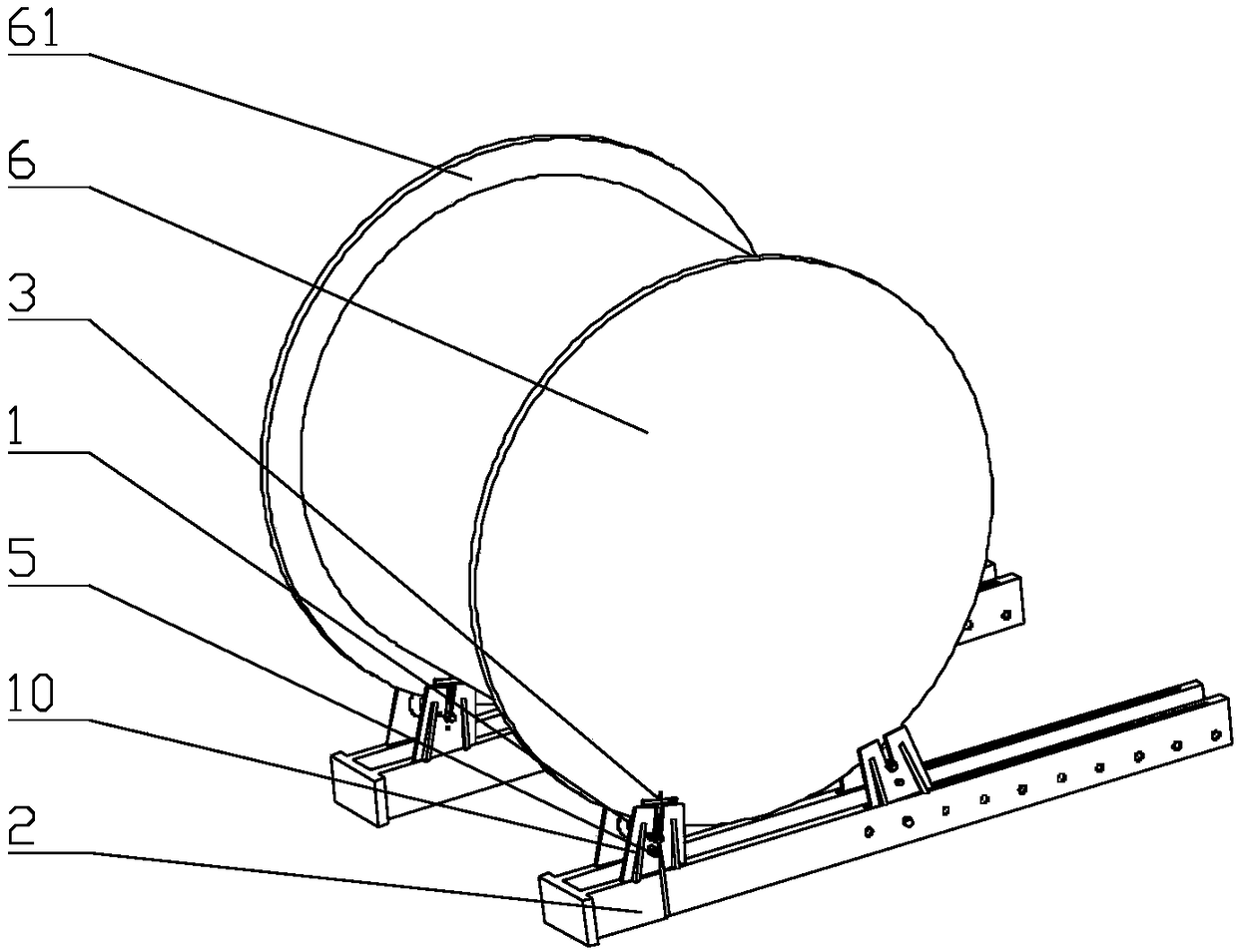
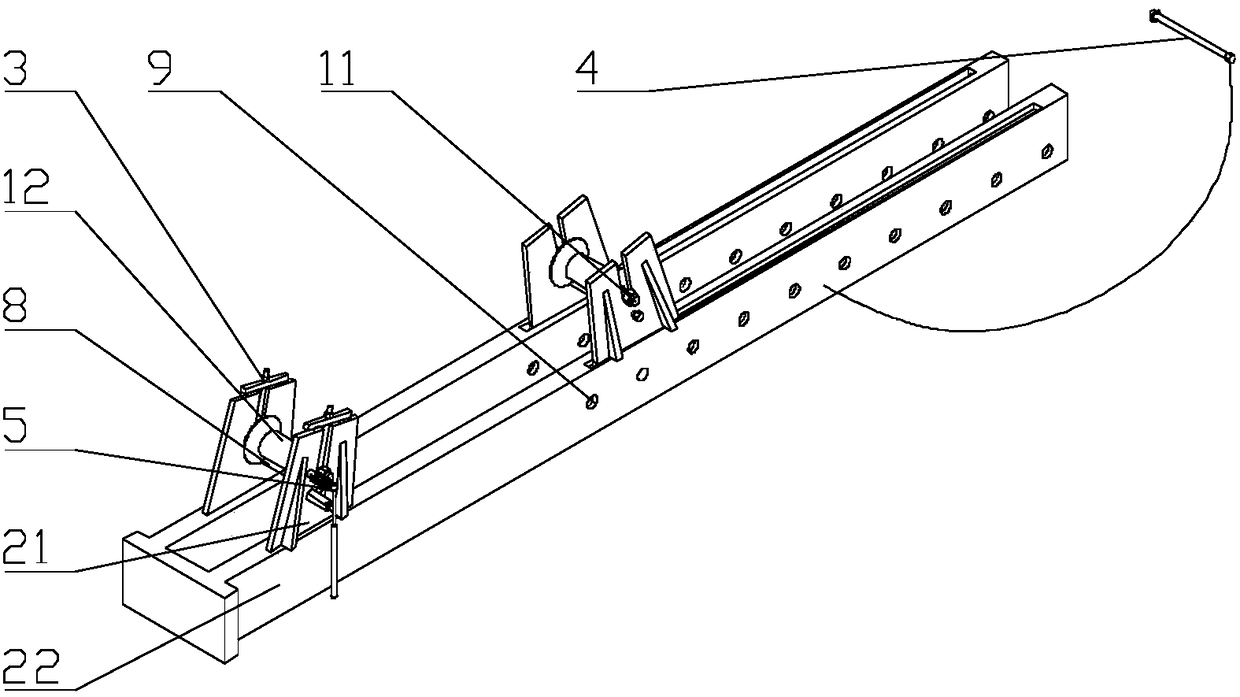
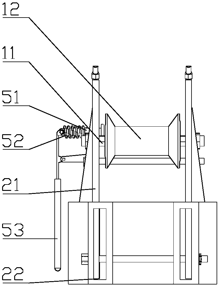
[0030] Attached figure 1 with figure 2 , Lifting type extension device with lever handbrake, including roller 1, split bracket 2, lifting device 3, locking pin 4 and lever handbrake device 5; said split bracket 2 includes bracket 21 and fixed connecting piece 22, the The fixed connecting memb...


PUM


Abstract

The invention provides a lifting type wire unwinding device with a lever hand brake. A fixed type roller structure small in size is adopted, space is greatly saved, the weight is small, carrying, loading and unloading are easy, and transportation and storage management are facilitated. A locking pin is arranged, and therefore a wire coil is placed on positioned and locked rollers in the transporting process and can be used more conveniently and quickly; discs of the wire coil are supported independently, wire coil friction in the unwinding process is avoided, adjustment is not needed, the working efficiency is high, and limitation to road traffic polices is avoided; the distance between the two rollers is adjusted, the wire coil can be placed more stably and reliably, and adjustment and use are more convenient and flexible; the lever hand brake device is arranged, the rotating speed of the wire coil is controlled, and orderly wire coil unwinding according to actual condition in actualconstruction can be guaranteed; and the lifting type wire unwinding device is simple in structure, convenient and quick to install and operate, recyclable, economical, practical, reasonable in design,compact in structure and suitable for wide popularization.

Description

Technical field [0001] The invention relates to the technical field of auxiliary equipment for power systems, and in particular to a lift-type wire extension device with a lever hand brake. Background technique [0002] Conventional wire pay-off brackets and spool trays have the following problems: 1. The pay-off racks are large in size and weight, occupying transportation space and laborious loading and unloading; 2. Large iron bars are required to support the spools, which are extremely heavy and require two people to lift them. Handling and moving consumes a lot of manpower and increases the transportation volume; 3. It is easy to cause the spool to rub against the pay-off bracket during the laying-out process, which needs to be adjusted, which affects the work efficiency; 4. When the spool is transported by a gun truck, the road traffic police checks the buckle Cars and artillery carts need to have brakes and complete lighting; 5. Due to the high center of gravity, the bracke...

Claims


Application Information

Patent Timeline
Patent Type & Authority Applications(China)
IPC IPC(8): B65H75/30B65H75/14B65H49/36
CPCB65H49/36B65H75/14B65H75/30B65H2701/34
Inventor 冯志华白国峰
Owner 国网安徽省电力有限公司亳州供电公司
Why Eureka
Try Eureka