Lifting type split wire coil pay-off device

A pay-off device, lift-type technology, applied in the field of lift-type split wire reel pay-off device, can solve the problems of large volume and weight of the pay-off frame, wire reel friction pay-off support, and easy safety accidents, etc., to achieve structural Simple, stable and reliable placement, convenient installation and operation

Pending Publication Date: 2018-09-04
国网安徽省电力有限公司亳州供电公司 +1
View PDF13 Cites 3 Cited by
  • Summary
  • Abstract
  • Description
  • Claims
  • Application Information

AI Technical Summary

Problems solved by technology

[0002] Conventional wire pay-off brackets and wire reel trailers have the following problems: 1. The pay-off rack is large in size and weight, takes up transportation space, and requires laborious loading and unloading; 2. A large iron bar is required to support the wire reel, which is very heavy and requires two people to carry it Carrying and moving consumes a lot of manpower and increases the transportation volume; 3. During the unwinding process, it is easy to cause the reel to rub against the pay-off bracket, which needs to be adjusted to affect work efficiency; Vehicles and artillery vehicles need to have brakes and complete lights; 5. Due to the high center of gravity, the bracket area is small, unstable, and can be tilted and hurt people; 6. The improper use of the shaft bracket of the reel bracket causes personal injury and death accidents; 7. Assembling the pay-off frame requires many people to complete, and the labor intensity is high; 8. There is no special equipment to control the pay-off speed during display, which is prone to safety accidents, so it is necessary to develop a pay-off device

Method used


Image

  • Lifting type split wire coil pay-off device
  • Lifting type split wire coil pay-off device
  • Lifting type split wire coil pay-off device

Examples


Embodiment Construction

[0030] In order to make the purpose, technical solutions and advantages of the embodiments of the present invention clearer, the technical solutions in the embodiments of the present invention will be clearly and completely described below in conjunction with the embodiments of the present invention. Obviously, the described embodiments are part of the present invention Examples, not all examples. Based on the embodiments of the present invention, all other embodiments obtained by persons of ordinary skill in the art without creative efforts fall within the protection scope of the present invention.

[0031] In conjunction with accompanying drawing, the present invention will be further described:

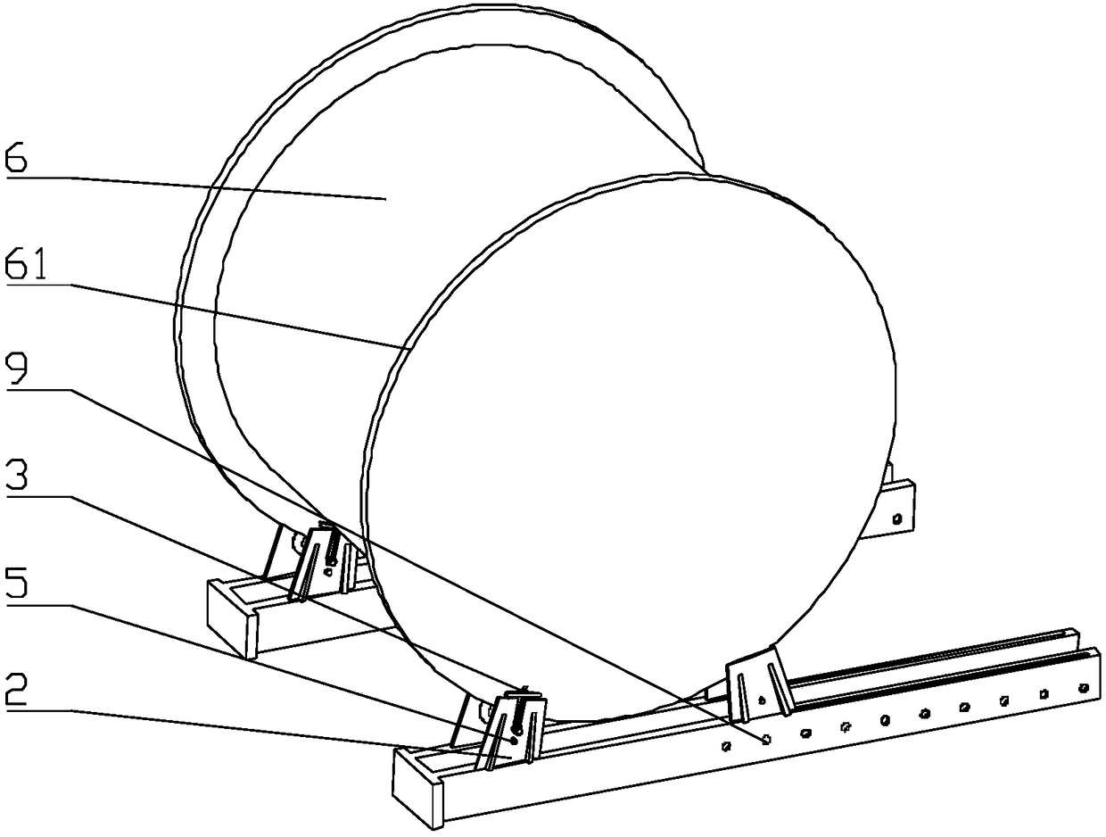
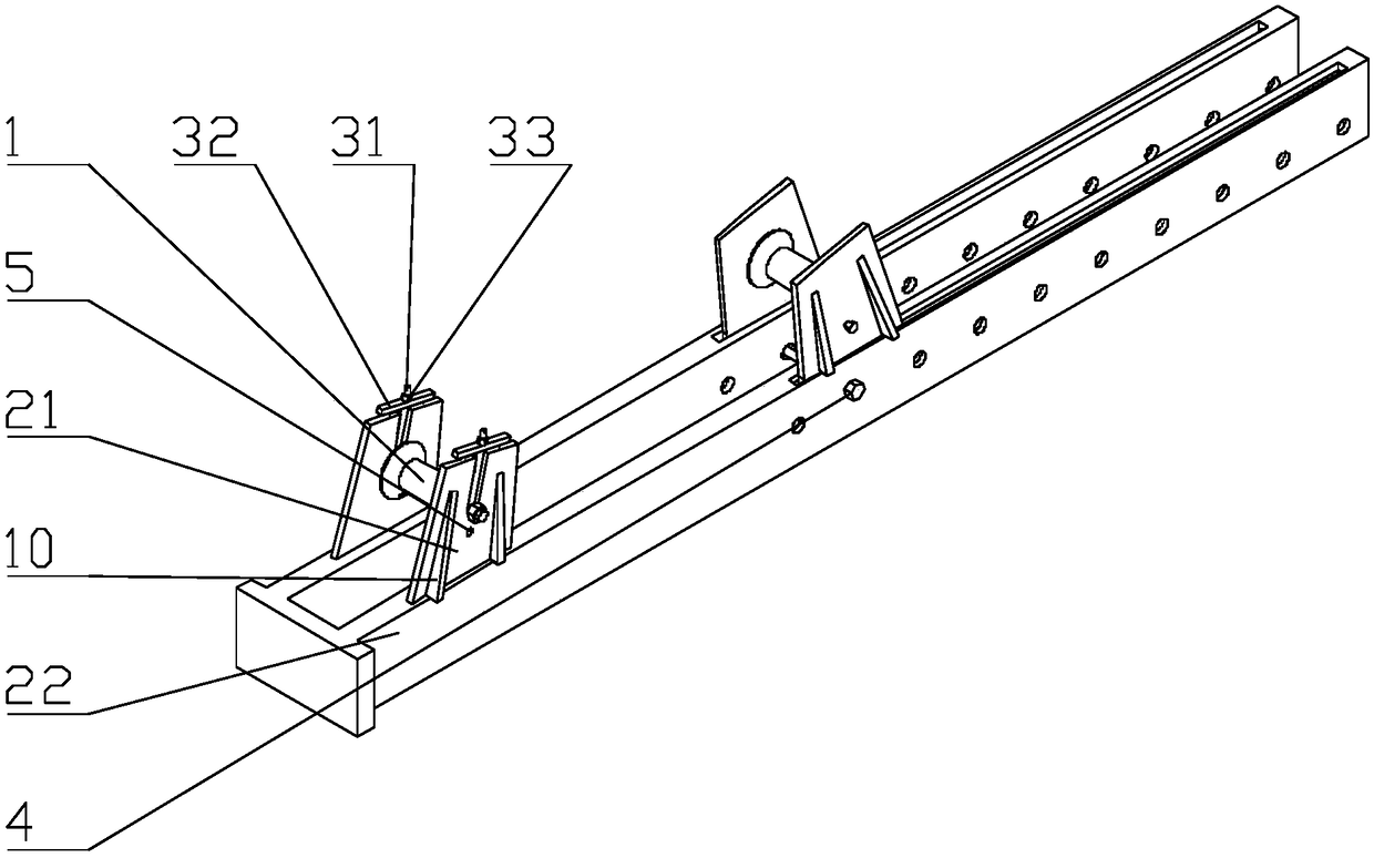
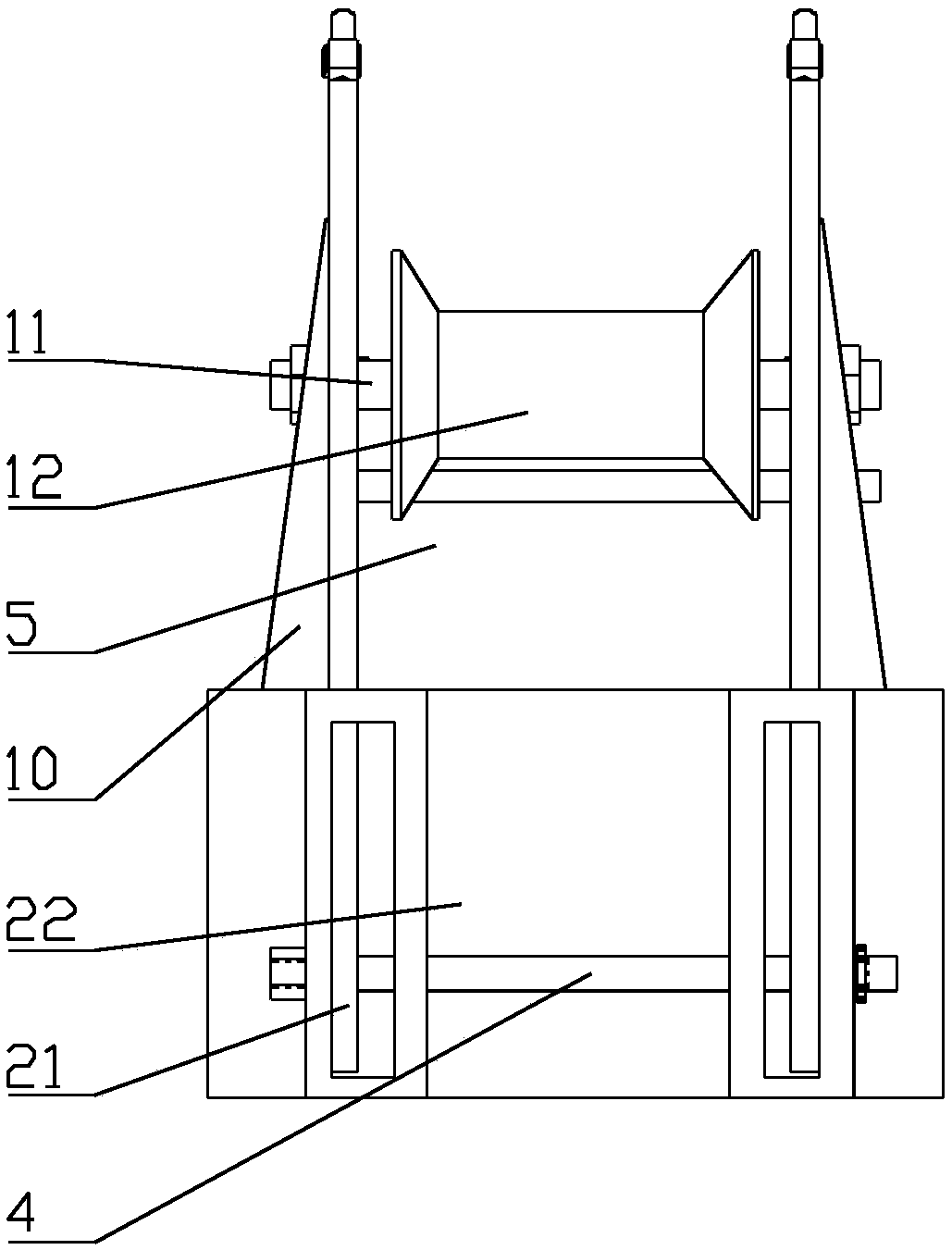
[0032] combined with figure 1 and figure 2 , a lift-type split wire reel pay-off device, including a roller 1, a split bracket 2, a lifting device 3 and a locking pin 4; the split bracket 2 includes a bracket 21 and a fixed connector 22, and the fixed connector 22 is A structur...


PUM


Abstract

The invention provides a lifting type split wire coil pay-off device. According to the lifting type split wire coil pay-off device, by using a fixed rolling wheel structure with the small size, the space is saved greatly, the weight is low, the lifting type split wire coil pay-off device is easy to carry, load and unload, the transportation workload is low, the manpower is saved, and transportation and storage management are facilitated. By arranging locked pins, the purposes that a wire coil can be put on positioned and locked rolling wheels in the transportation process and is more convenient and faster to use are realized; by supporting discs of the wire coil, the friction of the wire coil is avoided in the pay-off process, no adjustment is needed, the working efficiency is high, and the limitation by the road traffic police is avoided; and by adjusting the distance between the two rolling wheels, the center of gravity of containing of the wire coil is lowered, the placement of thewire coil is more stable and reliable, and the adjustment and use are more convenient and flexible. The lifting type split wire coil pay-off device has the beneficial effects of being simple in structure, convenient and fast to mount and operate, capable of being reused, economical, practical, reasonable in design, compact in structure and suitable for being widely popularized.

Description

technical field [0001] The invention relates to the technical field of electric power system auxiliary equipment, in particular to a lift-type split reel pay-off device. Background technique [0002] Conventional wire pay-off brackets and wire reel trailers have the following problems: 1. The pay-off rack is large in size and weight, takes up transportation space, and requires laborious loading and unloading; 2. A large iron bar is required to support the wire reel, which is very heavy and requires two people to carry it Carrying and moving consumes a lot of manpower and increases the transportation volume; 3. During the unwinding process, it is easy to cause the reel to rub against the pay-off bracket, which needs to be adjusted to affect work efficiency; Vehicles and artillery vehicles need to have brakes and complete lights; 5. Due to the high center of gravity, the bracket area is small, unstable, and can be tilted and hurt people; 6. The improper use of the shaft bracke...

Claims


Application Information

Patent Timeline
Patent Type & Authority Applications(China)
IPC IPC(8): B65H49/32
CPCB65H49/32
Inventor 冯志华
Owner 国网安徽省电力有限公司亳州供电公司
Why Eureka
Try Eureka