Connecting rod experimental device for simulating rotor rub-impact faults

A technology for simulating rotors and test devices, applied in the field of test devices and connecting rod test devices for simulating rotor rubbing faults, can solve problems such as reducing reliability and stability, economic losses, and inability to achieve local surface contact.

Pending Publication Date: 2018-08-17
HARBIN ELECTRIC CO LTD
View PDF6 Cites 1 Cited by
  • Summary
  • Abstract
  • Description
  • Claims
  • Application Information

AI Technical Summary

Benefits of technology

The present technology allows for accurate simulation of rubber-contacting surfaces on a machine's rollers during operation without requiring excessive maintenance or adjustment from other parts that are already working properly. This results in improved efficiency and reliability over time.

Problems solved by technology

This patented describes how it can be difficult for conventional testing equipment used during designing or manufacturing processes due to high levels of noise generated by these machines that causes damage from collisions between moving parts. Existing tests are limited because they only partially touch surfaces with fixed contacts and may require manual adjustment over time.

Method used


Image

  • Connecting rod experimental device for simulating rotor rub-impact faults
  • Connecting rod experimental device for simulating rotor rub-impact faults

Examples


Embodiment Construction

[0014] Preferred embodiments of the present invention will be described in detail below with reference to the accompanying drawings.

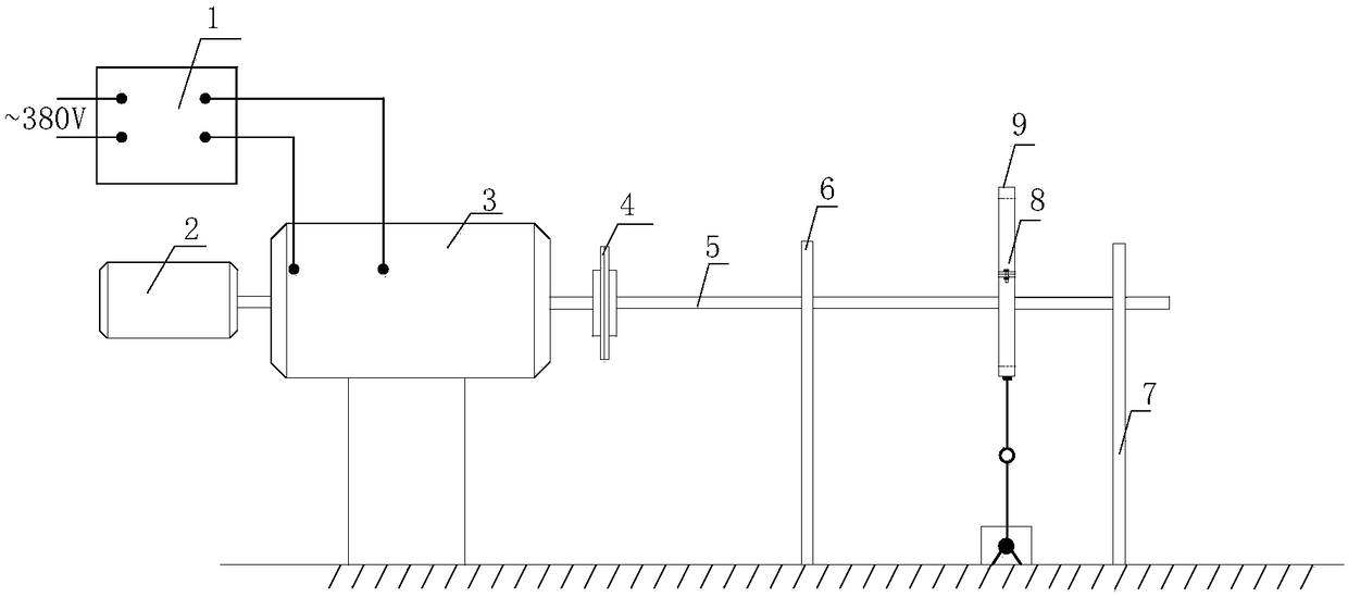
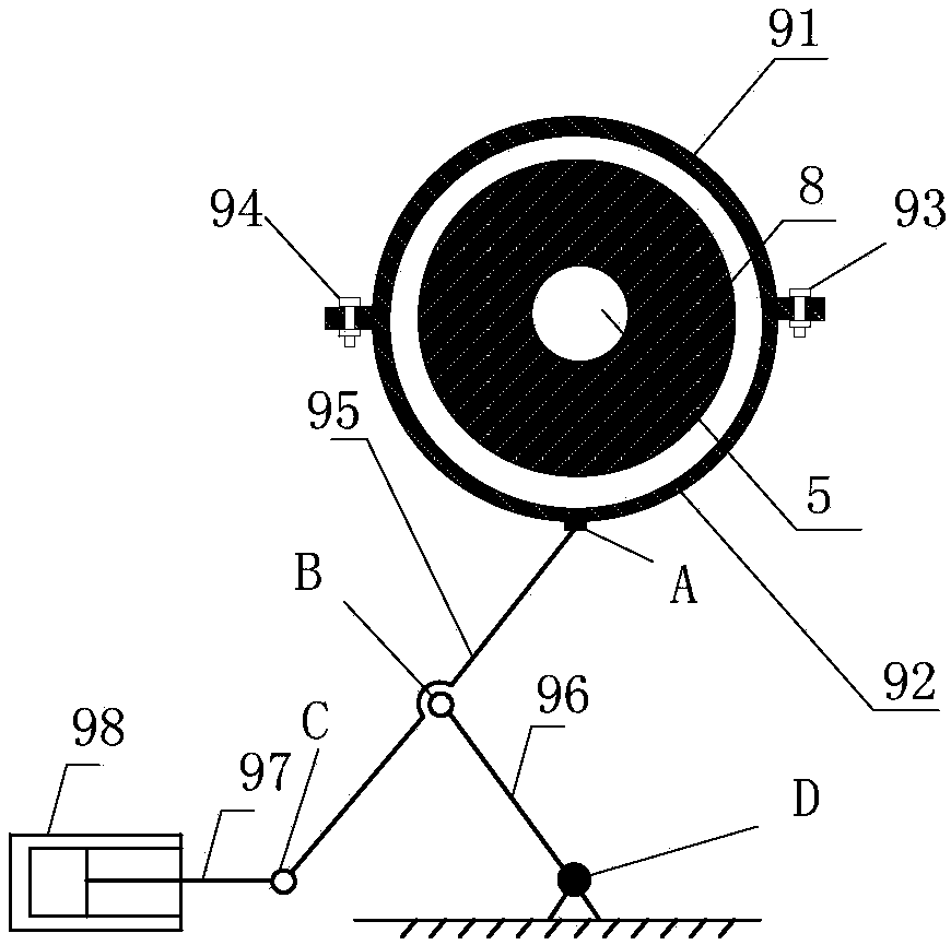
[0015] Such as figure 1 and figure 2 As shown, a connecting rod test device for simulating a rotor friction failure according to the present invention includes a control cabinet 1, a speed measuring motor 2, a DC motor 3, a rotating shaft 5, a first bearing seat 6, a second bearing seat 7, and a turntable 8 And connecting rod rubbing device 9;

[0016] The DC motor 3 and the connecting rod rubbing device 9 are all fixed on the working platform, and the center line of the DC motor 3 and the connecting rod rubbing device 7 are on the same straight line, the speed measuring motor 2 is installed on the DC motor 3, and the DC motor 3 is electrically connected to the control cabinet 1, the output end of the DC motor 3 is connected to one end of the rotating shaft 5, and the other end of the rotating shaft 5 passes through the first bearing seat 6,...


PUM


Abstract

The invention discloses a connecting rod experimental device for simulating rotor rub-impact faults, belongs to the technical field of rotor rub-impact experiments, and aims to solve the problems thatan existing experimental device cannot adjust contact depth of a rub-impact contact piece and rotor and cannot simulate the rub-impact faults from weakness to severity. A direct current dynamo and aconnecting rod rub-impact device are both fixed to a working platform, center lines of the direct current dynamo and connecting rod rub-impact device are in the same straight line, and a speed measuring motor is arranged on the direct current dynamo; the direct current dynamo is electrically connected with a control cabinet, the output end of the direct current dynamo is connected with one end ofa rotary shaft, and the other end of the rotary shaft successively penetrates through a first baring pedestal, a turnplate and a second bearing pedestal; the first bearing pedestal and the second bearing pedestal are fixedly arranged on the working platform, the turnplate is located inside the connecting rod rub-impact device, and a mounting gap is reserved between the turnplate and the connectingrod rub-impact device. The connecting rod experimental device for simulating rotor rub-impact faults can accurately simulate rotor rub-impact faults of different depths and local face contact.

Description


Claims


Application Information

Patent Timeline
Owner HARBIN ELECTRIC CO LTD
Why Eureka
Try Eureka