
A test device for thermal shock resistance performance of batch test pieces

A technology of thermal shock resistance and testing equipment, applied in the direction of measuring equipment, strength characteristics, instruments, etc., can solve the problems of limited target range, low test efficiency, high temperature radiation of heating furnace, etc., and achieve wide experimental range, wide application range, and reliability sex high effect

Active Publication Date: 2020-12-11
CHONGQING UNIV
View PDF7 Cites 0 Cited by
  • Summary
  • Abstract
  • Description
  • Claims
  • Application Information

AI Technical Summary

Problems solved by technology

[0004] 1. The initial temperature of thermal shock can only be room temperature, and the thermal shock test of heating up under different initial temperature conditions cannot be realized.
[0005] The experimental range of the thermal shock resistance performance of the test piece is narrow;
[0006] 2. Only one test piece can be clamped in one test, and it takes a long time and the test efficiency is low;
[0007] 3. There is no special chamber designed to store the test piece before the thermal shock test, and the clamping test piece is relatively close to the heating furnace, and the initial temperature is easily affected by the high temperature radiation of the heating furnace
[0008] The above problems will make this test box only able to realize the temperature rise thermal shock test under the condition of small temperature difference, and the initial ambient temperature of the thermal shock of the specimen is limited to room temperature and cannot be adjusted, the target range is limited, and the experimental results cannot well characterize the resistance of the material. Thermal shock performance, the characterization results of thermal shock resistance obtained in one experiment are less and the efficiency is low

Method used


Image

  • A test device for thermal shock resistance performance of batch test pieces
  • A test device for thermal shock resistance performance of batch test pieces

Examples


Embodiment Construction

[0016] Below in conjunction with accompanying drawing and embodiment the present invention will be further described:

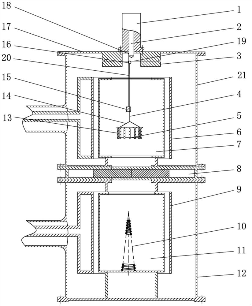
[0017] Such as figure 1 As shown, the present invention includes an upper sealed furnace 21 and a lower sealed furnace 12, the two sealed furnaces are vertically connected in series, a sealed and heat-insulated door 8 is arranged in the middle, and a furnace door 17 is installed on the top, and the furnace door 17 is fixedly installed with Cylinder 1, the pneumatic plunger 2 in the cylinder 1 can be stretched in the upper sealing furnace 21; The upper heating furnace 6 in the upper sealing furnace 21 can build the upper high temperature chamber 7, and there is a specimen rack 14 in the upper high temperature chamber 7; The lower surface of the door 17 has a suspension wire column 3, the two ends of the suspension wire 19 are fixed on the suspension wire column 3, the top of the suspension wire 3 20 is fixed on the furnace door 17, and a weight 15 is hung on t...


PUM


Abstract

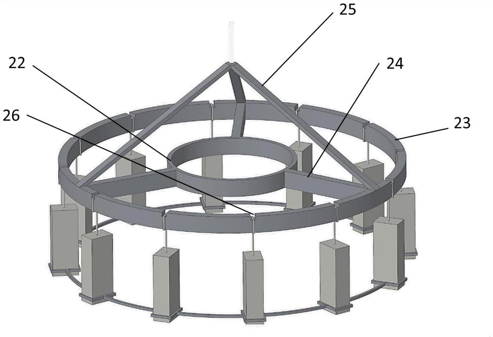
The invention discloses a device for testing the thermal shock resistance of batch test pieces. The device comprises a cylinder, a pneumatic punch, an upper sealing furnace, a heat insulation bin doorand a lower sealing furnace. An upper high temperature chamber is built in an upper heating furnace, and a test piece holder is arranged in the upper high temperature chamber. The upper ends of the test pieces hang on the test piece holder, and the lower ends of the test pieces are fixed by a test piece sleeve. The top of the test piece holder is connected with a first suspension wire, a guidingring is arranged at the top of the first suspension wire, and the guiding ring simultaneously goes through a second suspension wire and a third suspension wire. The second suspension wire is fixed ona suspension wire column, the top of the third suspension wire is fixed on a furnace door, and a weight hangs at the lower end of the third suspension wire. A lower high temperature chamber is built in the lower heating furnace, and a spiral test piece tower is arranged at the bottom of the lower high temperature chamber. In the test of the thermal shock resistance of a material, the initial environment of the test pieces is any temperature, and the range of the thermal shock resistance experiments of the test pieces is wide; multiple parameters and high efficiency are obtained through the experiments for one-time performance detection of the thermal shock resistance of a plurality of the test pieces; and the thermal shock test object environment consistence of the test pieces in the samebatch is good, and a test result has a high reliability.

Description

technical field [0001] The invention belongs to the testing technology of thermal shock resistance performance of materials, and in particular relates to a thermal shock resistance testing device of batch test pieces. Background technique [0002] With the rapid development of high-temperature fields such as aerospace, nuclear industry and petrochemical industry, traditional material systems can no longer meet the application requirements, and it is extremely urgent to develop new high-temperature materials that can be applied to complex and harsh working conditions. However, the existing theoretical analysis of high temperature mechanics, especially the theoretical analysis of the thermal shock resistance of materials suitable for diverse and complex thermal shock environments, is quite lacking at home and abroad. One of the main reasons is the lack of reasonable and effective experimental results. support. It takes a long time (usually >4h) to obtain the required high-...

Claims


Application Information

Patent Timeline
Patent Type & Authority Patents(China)
IPC IPC(8): G01N3/60
CPCG01N3/60
Inventor 李卫国张欣寇海波麻建坐邓勇邵家兴张续耀李莹张先贺徐念东董攀陶勇方岱宁
Owner CHONGQING UNIV
Learn More