Monitoring method of mold cooling pipeline

A technology for cooling pipes and mold cooling, which is applied in the testing of mechanical components, testing of machine/structural components, measuring devices, etc., and can solve problems such as complex cooling systems, increased processing, and poor cooling effects

Active Publication Date: 2018-08-21
GUANGZHOU DIE & MOLD MFG
View PDF8 Cites 5 Cited by
  • Summary
  • Abstract
  • Description
  • Claims
  • Application Information

AI Technical Summary

Problems solved by technology

[0002] In the design of die-casting molds, the design of cooling pipes plays a vital role in the molding quality of products. If the cooling effect is not good, die-casting products are prone to shrinkage cavities, mold sticking to aluminum and other defects.
To solve these problems, a reasonable mold cooling system design is the first condition. However, under the premise of a reasonable cooling system design, the processing conditions of the mold cooling pipeline and the installation level of the cooling parts will also have a huge impact on the cooling of the mold.
Nowadays, in order to achieve a good cooling effect for the cylinder block mold, the cooling system is very complicated. Sometimes the water delivery hole of the coolant has two angles at the same time, which adds a lot of difficulty to the processing. The case where the water hole processing is not connected

Method used


Image

  • Monitoring method of mold cooling pipeline

Examples


Embodiment Construction

[0023] A monitoring method for a mold cooling pipeline, the principle of which is:

[0024] S1, pass a cooling liquid of a specific pressure to the inlet of the cooling pipe of the mold to be monitored;

[0025] S2, obtain the detected flow value of the cooling liquid at the outlet of the cooling pipe of the mold to be monitored within a specified time;

[0026] S3, repeat the above-mentioned steps S1 and S2 at least once to obtain several detected flow values, and average each detected flow value as the monitored flow value;

[0027] S4, by comparing the monitored flow rate value and the standard flow rate value, it is judged whether the cooling pipe of the mold to be monitored is qualified.

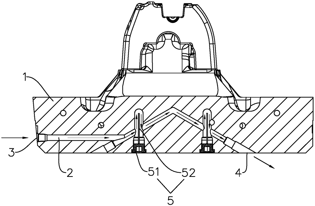
[0028] In an embodiment, refer to figure 1 , shows a lower mold 1, which is arranged with a cooling pipe 2. The cooling pipe 2 is composed of a plurality of cooling water holes arranged in the lower mold 1. Similarly, the diameter of each cold water hole is selected according to the ...


PUM


Abstract

The invention discloses a monitoring method of a mold cooling pipeline, and relates to the technical field of molds. The monitoring method comprises the following steps of S1, introducing specific-pressure cooling fluid into an inlet of a to-be-monitored mold cooling pipeline; S2, obtaining the detected flow value, within an appointed time, of the cooling fluid in the outlet of the to-be-monitoredmold cooling pipeline; S3, at least once repeating the steps S1 and S2, so as to obtain a plurality of the detected flow values, averaging the detected flow values and then using as a monitored flowvalue; S4, through comparing the monitored flow value and a standard flow value, judging whether the to-be-monitored mold cooling pipeline is qualified or not. According to the monitoring method, through introducing the specific-pressure cooling fluid into the to-be-monitored mold cooling pipeline to subsequently obtain the plurality of the detected flow values within a certain time, the detectedflow values are averaged; afterwards, an obtained average value is used as the monitored flow value; the monitored flow value is compared with the standard flow value, and in the condition that a partin the interior of the mold cannot be seen, whether the to-be-monitored mold cooling pipeline is qualified or not can be quickly judged.

Description

technical field [0001] The invention relates to the technical field of molds, in particular to a monitoring method for cooling pipes of a mold. Background technique [0002] In the design of die-casting molds, the design of cooling pipes plays a crucial role in the molding quality of the products. The cooling effect is not good, and the die-casting products are prone to shrinkage holes, mold sticking to aluminum and other defects. To solve these problems, a reasonable mold cooling system design is the primary condition. However, under the premise of a reasonable cooling system design, the processing conditions of the mold cooling pipes and the installation level of the cooling parts will also have a huge impact on the cooling of the mold. . In order to achieve a good cooling effect, the cooling system of the cylinder mold is very complicated. Sometimes the water transport hole of the coolant has two angles at the same time, which adds a lot of difficulty to the processing. ...

Claims


Application Information

Patent Timeline
Patent Type & Authority Applications(China)
IPC IPC(8): B22D17/22G01M13/00
CPCB22D17/2218G01M13/00
Inventor 周于铭何炽灵陈岳军朱冠帷
Owner GUANGZHOU DIE & MOLD MFG
Why Eureka
Try Eureka