Multifunctional test platform of loudspeaker
A multi-functional testing and speaker technology, applied in the direction of electrical components, etc., can solve the problems of the test equipment with few functions, few test items, and inability to adapt to various types of speakers, etc., to achieve various test functions and good test results Effect
- Summary
- Abstract
- Description
- Claims
- Application Information
AI Technical Summary
Problems solved by technology
Method used
Image
Examples
Embodiment 1
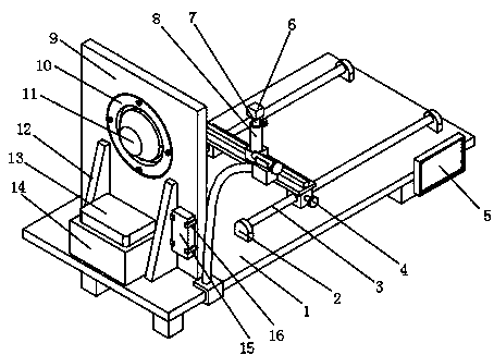
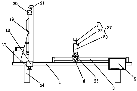
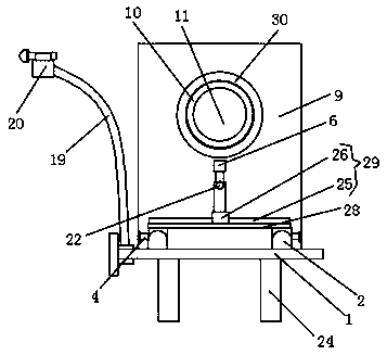
[0018] Embodiment 1: A multifunctional test platform for a speaker, comprising a table board 1, four legs 24 are distributed on the lower surface of the table board 1, and a fixing plate 9 is connected to the left side of the upper surface of the table board 1 through a reinforcement board 12, The structural strength is increased by the reinforcement plate 12, and the fixed plate 9 is vertically arranged with the table top 1, and a retaining ring 30 is arranged in the hole in the middle of the left surface of the fixed plate 9, and the left surface of the retaining ring 30 is connected with a movable ring 10 by a mounting stud. , the middle part of the movable ring 10 is provided with a speaker 11. When the model of the speaker 11 is relatively large, the movable ring 10 is disassembled, and the speaker 11 is directly connected to the retaining ring 30, which is convenient for adapting and installing various types of speakers. The left side of the surface is provided with an au...
Embodiment 2
[0023] The difference between this embodiment and embodiment 1 is:
[0024] In this embodiment, the front surface of the table board 1 is provided with a U-shaped block 18, and a second fastening stud 17 is threaded in the screw hole on the lower surface of the U-shaped block 18, and the end of the second fastening stud 17 is connected to the Table 1 contacts, and the upper surface of U-shaped block 18 is provided with gooseneck 19, and the upper end of gooseneck 19 is connected with microphone 21 through placement block 20, and the output end of microphone 21 is electrically connected with the input end of power amplifier module 13.
[0025] Specifically, the microphone 21 can be used to speak to the power amplifier module 13, adding a test method, and when the gooseneck 19 is twisted, the microphone 21 can be driven to move.
Embodiment 3
[0027] The difference between this embodiment and embodiment 1 is:
[0028] In this embodiment, the sliding structure 29 includes a sliding bar 25, the sliding bar 25 is arranged on the upper surface of the connecting bar 28, the upper surface of the sliding bar 25 is slidably connected with the second slider 26, and the telescopic mechanism 27 includes a sleeve 8, the sleeve 8 is arranged on the upper surface of the second slide block 26, and the middle part of the casing 8 is provided with a movable column 7, and a third fastening stud 22 is threaded in the screw hole on the side surface of the casing 8, and the third fastening stud 22 The end of the contact with the side surface of the movable column 7.
[0029] Specifically, the second slider 26 can slide on the slide bar 25, and the position of the test can be changed. The movable column 7 can move in the sleeve pipe 8, which is convenient for adjusting the height of the wave recorder 6, and can test the sound of differen...
PUM
 Abstract
Description
Claims
Application Information
 - R&D
- Intellectual Property
- Life Sciences
- Materials
- Tech Scout
- Unparalleled Data Quality
- Higher Quality Content
- 60% Fewer Hallucinations
Browse by: Latest US Patents, China's latest patents, Technical Efficacy Thesaurus, Application Domain, Technology Topic, Popular Technical Reports.
© 2025 PatSnap. All rights reserved.Legal|Privacy policy|Modern Slavery Act Transparency Statement|Sitemap|About US| Contact US: help@patsnap.com


