Check patentability & draft patents in minutes with Patsnap Eureka AI!

An oled drive circuit

A driving circuit and branch circuit technology, applied to static indicators, instruments, etc., can solve the problem of insufficient charging of display panel pixels

Active Publication Date: 2020-09-11
EVERDISPLAY OPTRONICS (SHANGHAI) CO LTD
View PDF7 Cites 0 Cited by
  • Summary
  • Abstract
  • Description
  • Claims
  • Application Information

AI Technical Summary

Problems solved by technology

[0005] The present invention provides an OLED driving circuit, which is used to solve the problem in the prior art that some pixels of a display panel are insufficiently charged, resulting in obvious vertical stripes with alternating light and dark on the display panel.

Method used


Image

  • An oled drive circuit
  • An oled drive circuit
  • An oled drive circuit

Examples


Embodiment Construction

[0054] In order to make the technical problems, technical solutions and effects solved by the present invention clearer, the preferred embodiments of the present invention will be described below in conjunction with the accompanying drawings. It should be understood that the preferred embodiments described here are only used to illustrate and explain the present invention. Invention is not intended to limit the present invention. And in the case of no conflict, the embodiments in the present application and the features in the embodiments can be combined with each other.

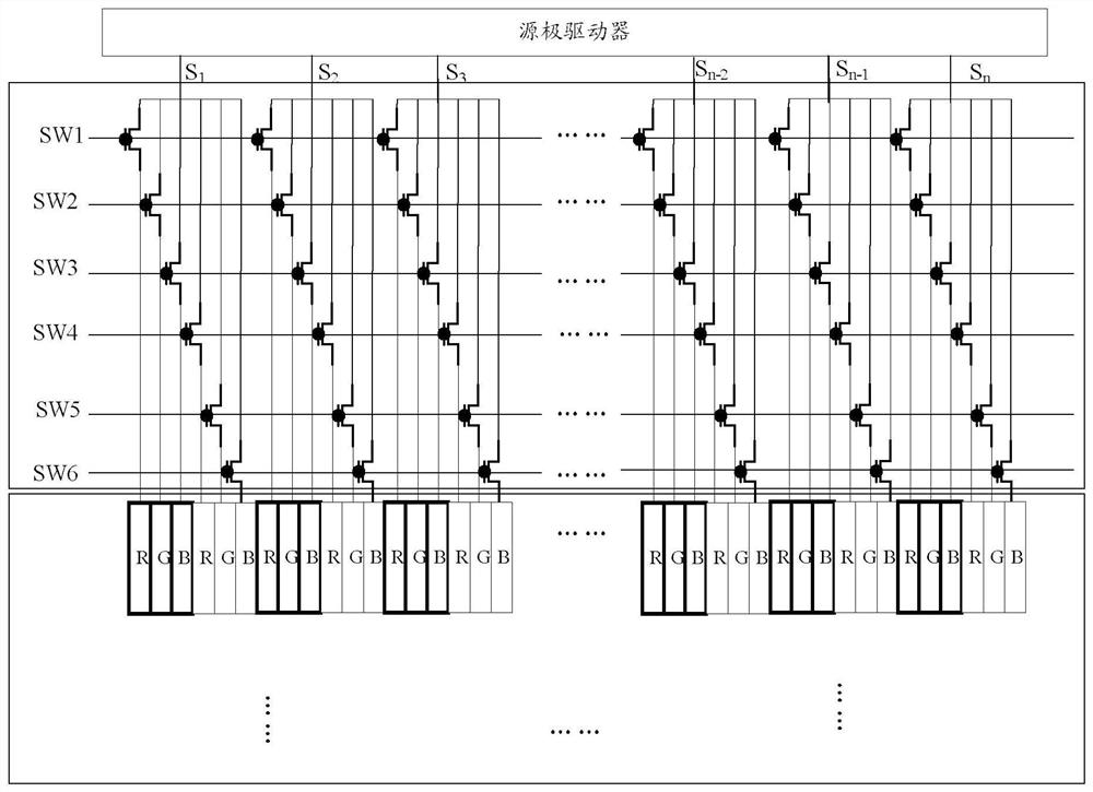
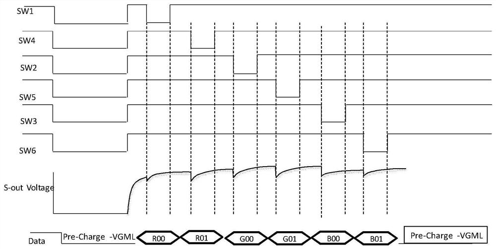
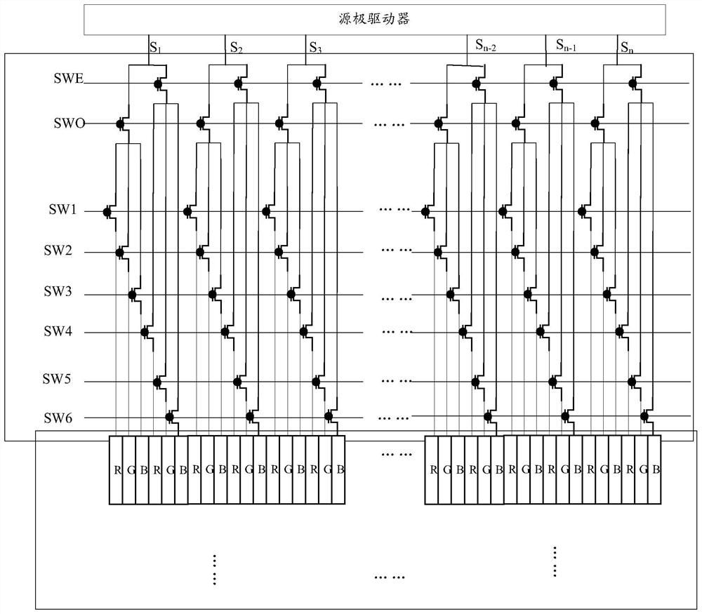
[0055] Such as image 3 As shown, the embodiment of the present invention provides an OLED driving circuit, including multiple rows and columns of sub-pixels arranged in an array, data lines corresponding to the columns where the sub-pixels are located, and gate lines corresponding to the rows where the sub-pixels are located, including:

[0056] source driver, gate driver and N multiplexing control modules...


PUM


Abstract

The invention discloses an OLED (Organic Light Emitting Diode) driving circuit, which comprises N multiplex control modules and N data signal output channels, wherein each data signal output channel is at least electrically connected with first to sixth data lines which are vertically arranged in sequence through one multiplex control module; each multiplex control module comprises a first shunt switch element and a second shunt switch element which are connected to the same data signal output channel and first to sixth branch switch elements which are electrically connected with the first tosixth data lines respectively; the first to third branch switch elements are connected to the first shunt switch element in parallel; the fourth to sixth branch switch elements are connected to the second shunt switch element in parallel; and the first shunt switch element and the second shunt switch element are different in sequence of alternate conduction when a gate driving signal scans odd-numbered lines and even-numbered lines of a sub-pixel array, thereby enabling the display brightness of the sub-pixels to be irregularly distributed, and thus achieving a purpose of weakening the fringes.

Description

technical field [0001] The embodiments of the present invention relate to the field of display technology, and in particular to an OLED driving circuit. Background technique [0002] For small-sized AMOLED (Active-matrix organic light emitting diode, active-matrix organic light-emitting diode) products, the source driver is usually driven by multiplexing. In order to reduce the number of circuits on the periphery of the driver chip, the A switch array needs to be added to the display panel to divide the Sourcechannel signal output by the Driver IC into different equal parts, and each equal part is written by a switch control data, and the corresponding Pixel array display content is written to reduce the area of ​​the IC, thereby cut costs. [0003] For example, if figure 1 The display panel shown includes a source driver and a display pixel array, and every six columns of sub-pixels (R00, G00, B00, R01, G01, B01) is a group of pixels, and the first group of pixels receive...

Claims


Application Information

Patent Timeline
Patent Type & Authority Patents(China)
IPC IPC(8): G09G3/3225
CPCG09G3/3225G09G2320/0233
Inventor 王建刚
Owner EVERDISPLAY OPTRONICS (SHANGHAI) CO LTD
Features
  • R&D
  • Intellectual Property
  • Life Sciences
  • Materials
  • Tech Scout
  • Unparalleled Data Quality
  • Higher Quality Content
  • 60% Fewer Hallucinations
Learn More