
Eureka
For R&D, Eureka makes reading and utilizing patents & technical documents easy.
Eureka AIR
Designed for self-driven R&D workflows. Generate viable solutions, solve complex R&D challenges, empower your innovation with AI.

Eureka Materials
Designed for material experts only. Revolutionize your material R&D, from search, analyze, to developing new materials.

TechResearch
Generate reliable direction feasibility study reports for your R&D in just a few steps.

TechSeek
Discover and master advanced knowledge NOW. Basics, ideas, possibilities, all at once.

TechMind
As an expert in R&D Theories, TechMind can generates customized viable solutions instantly.

TechRisk
Analyze your overall solution with one click, know your potential R&D risks in advance.

TechMonitor
Get weekly tech updates, stay abreast of the latest tech innovations and key insights.
Method for determining injection start time and injection quantity of fuel
A technology of injection start and fuel injection, applied in fuel injection control, combustion engine, internal combustion piston engine, etc., can solve problems such as complex methods, inaccuracies, and errors
- Summary
- Abstract
- Description
- Claims
- Application Information
AI Technical Summary
Problems solved by technology
Method used
Image

Examples
Embodiment Construction
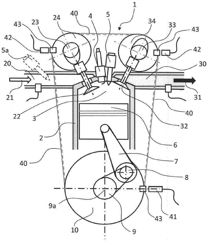
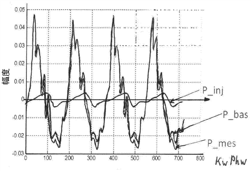
[0029] The invention is based on the insight that, on the assumption of intake-synchronized fuel injection, there is a unique relationship between the distribution of the intake manifold pressure oscillation signal and the injection start time and also the injection quantity of the fuel in the intake tract of an internal combustion engine.
[0030] In the method according to the invention, during normal operation, during intake-synchronized fuel injection, first at defined operating points, the cylinders assignable to the internal combustion engine in the inlet tract of the respective internal combustion engine are measured The dynamic pressure oscillation, and thus generate the corresponding pressure oscillation signal. At the same time, a crankshaft phase angle signal of the internal combustion engine is determined, so to speak, as a reference signal.
[0031] One possible operating point would be eg idle operation at a predetermined rotational speed. Here, intake-synchroni...
PUM
 Abstract
Description
Claims
Application Information
 - R&D Engineer
- R&D Manager
- IP Professional
- Industry Leading Data Capabilities
- Powerful AI technology
- Patent DNA Extraction
Browse by: Latest US Patents, China's latest patents, Technical Efficacy Thesaurus, Application Domain, Technology Topic, Popular Technical Reports.
© 2024 PatSnap. All rights reserved.Legal|Privacy policy|Modern Slavery Act Transparency Statement|Sitemap|About US| Contact US: help@patsnap.com