Waist force swing drive walking device
A technology of slewing drive and traveling device, which is applied in steering mechanism, transportation and packaging, steering mechanism of front and rear tandem vehicles, etc., can solve problems such as large operation blind spots, high cost, crop damage, etc. Simple, less crop damage effect
- Summary
- Abstract
- Description
- Claims
- Application Information
AI Technical Summary
Problems solved by technology
Method used
Image
Examples
Embodiment 1
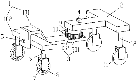
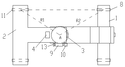
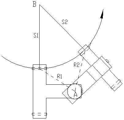
[0024] Such as figure 1 , figure 2 As shown, a kind of lumbar power rotation driving walking device of the present invention includes a front frame 1, a rear frame 2 and a running gear, and the running gear includes two front running gears and two rear running gears. In this embodiment, the walking The mechanism is a wheel, and of course the running mechanism can also be a walking track. Specifically, in this embodiment, the wheel includes two front wheels 8 and two rear wheels 11, and the front frame 1 includes a front support plate 102 and a front connecting frame 101, and the front connecting frame 101 connects the front support plate 102 through the horizontal rotation pair 5, the front support plate 102 connects the two front wheels 8 through the front bracket 6, and the rear frame 2 connects the two rear wheels 11 through the rear bracket 12, because the horizontal rotation pair 5 can Realize the relative rotation of the front connecting frame 101 and the front support...
Embodiment 2
[0028] Such as Figure 4 As shown, the structural principle of this embodiment is basically the same as that of Embodiment 1. The difference is that the rear frame 2 in this embodiment includes a rear support plate 202 and a rear connecting frame 201, and the rear connecting frame 201 passes through the horizontal rotation pair 5 Connect the rear support plate 202, the rear support plate 202 is connected to the rear wheel 11 through the rear support 12, the front vehicle frame 1 is connected to the front wheel 8 through the front support 6, and the front wheel 8 is connected to the driving device. The horizontal rotation pair realizes that the relative horizontal direction between the rear connecting frame 201 and the rear support plate 202 can be rotated. When the running device is walking on a complex road surface, the front running mechanism and the rear running mechanism can be in stable contact with the road surface at the same time, without stagnation in the air. Good fo...
Embodiment 3
[0030] The structural principle of this embodiment is basically the same as that of Embodiment 1. The difference is that in this embodiment, the horizontal rotation joint 5 used to realize the relative rotation in the horizontal direction between the front frame 1 and the rear frame 2 is provided with the rear frame 2 and the rear frame 2. Between the slewing drive, specifically, the outer ring 301 of the slewing support 3 of the slewing drive is connected to the front frame, the inner ring 302 is connected to the horizontal rotation pair 5 through the transmission shaft, and the horizontal rotation pair 5 is connected to the rear frame 2, and finally realized by the slewing drive. The vertical direction rotatable connection control between the front frame and the rear frame and the horizontal direction between the front frame and the rear frame are rotatable. Of course, the horizontal rotation joint 5 can also be arranged between the front frame 1 and the rotary drive. between...
PUM
 Abstract
Description
Claims
Application Information
 - R&D
- Intellectual Property
- Life Sciences
- Materials
- Tech Scout
- Unparalleled Data Quality
- Higher Quality Content
- 60% Fewer Hallucinations
Browse by: Latest US Patents, China's latest patents, Technical Efficacy Thesaurus, Application Domain, Technology Topic, Popular Technical Reports.
© 2025 PatSnap. All rights reserved.Legal|Privacy policy|Modern Slavery Act Transparency Statement|Sitemap|About US| Contact US: help@patsnap.com


