
Smart electric meter system with light wallet

A smart meter and wallet technology, applied in the direction of power network operating system integration, transmission system, digital transmission system, etc., can solve the problem of inability to adapt to transactions and records, distributed wind power photovoltaic and battery power collection, and the inability of electricity meters to realize point-to-point power transactions, etc. problems to achieve economically viable results

Pending Publication Date: 2018-08-24
HEPU TECH DEV BEIJING CO LTD
View PDF4 Cites 7 Cited by
  • Summary
  • Abstract
  • Description
  • Claims
  • Application Information

AI Technical Summary

Problems solved by technology

[0014] The purpose of the present invention is to provide a smart meter system with a light wallet. The smart meter system uses a block chain light wallet module, which solves the problem that the meter in the prior art cannot realize point-to-point power transactions, and the distributed wind power photovoltaic and The collection, transaction and recording of battery power and the inability to adapt to the needs of energy Internet big data

Method used


Image

  • Smart electric meter system with light wallet
  • Smart electric meter system with light wallet
  • Smart electric meter system with light wallet

Examples


Embodiment 1

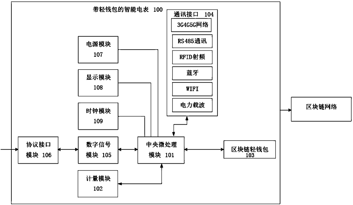
[0055] Please refer to figure 1 , figure 2 , the present invention provides a smart meter system with a light wallet, including: a central processing unit 101 , a metering module 102 , a blockchain light wallet module 103 and a communication module 104 . in:

[0056] The central processing unit 101 is used for processing and computing data in the smart meter 100 and controlling data exchange.

[0057] The metering module 102 is connected to the central processing unit 101 for one-way or two-way metering of electricity;

[0058] The blockchain light wallet module 103 is connected to the central processing unit 101 and performs data interaction with the central processing unit 101;

[0059] The communication module 104 is connected to the central processing unit 101, the metering module 102, and the blockchain light wallet module 103 wirelessly or wired, respectively, and is used to realize the data transmission between the metering module 102 and the blockchain light wallet...

Embodiment 2

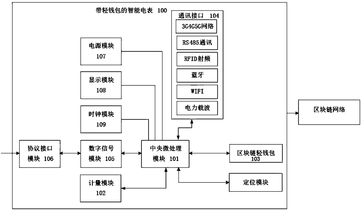
[0088] Please refer to image 3 The difference between this embodiment and Embodiment 1 is that, in this embodiment, the smart meter 100 further includes a positioning module connected to the central processing unit 101 for locating the geographical location of the smart meter 100 .

[0089] When the smart meter system in this embodiment is running, the location module locates the geographical location of the smart meter 100 to obtain the geographical location information of the blockchain nodes, and realizes the informationization of the geographical location of the entire smart grid. The optimal rationalization of chain point-to-point automatic power trading lays the foundation, that is, in the blockchain smart contract, it can be agreed that in the case of the same quotation, it is preferential to facilitate the power transaction between the two nodes with the closest geographical distance. Such power transmission costs and Lowest loss.

[0090] In this embodiment, the pos...

Embodiment 3

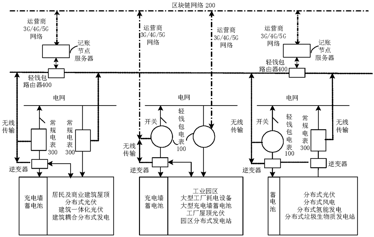
[0093] This embodiment is a smart meter system, including a conventional smart meter 300, the conventional smart meter 300 is provided with the central processing unit 101, the metering module 102 and the communication module 104, and also includes a block chain router 400, the The block chain router 400 is provided with the block chain light wallet module 103 and the communication module 104 .

[0094] In this embodiment, the functions and operation modes of each module of the smart meter system are the same as those in Embodiment 1.


PUM


Abstract

The invention discloses a smart electric meter system with a light wallet. The smart electric meter system includes a central processor, a metering module, a block-chain light wallet module and a communication module. According to the smart electric meter system, by adopting the block-chain light wallet module, the problem is solved that in the prior art, an electric meter cannot achieve point-to-point electricity trade and the collection, trade and record of the electric quantity of distributed wind-power photovoltaic power and storage batteries, and cannot meet the requirements of energy-internet big data; distributed electricity generation and storage and the bidirectional metering of the electricity generation quantity and electricity consumption quantity of electric consumers are achieved, therefore, the electric quantity of a distributed smart microgrid can be metered, traded and recorded, and a distributed electricity generation side and a distributed electricity consumption side are used as a basis of trade charging through a smart electric meter, so that the microgrid is more economically feasible.

Description

technical field [0001] The invention relates to the technical fields of smart meters and block chains, in particular to a smart meter system with a light wallet. Background technique [0002] Due to the uniqueness of the power system, a super huge network-grid is naturally formed from power generation, transmission and distribution to power consumption. At one end are traditional energy sources such as coal-fired gas, nuclear power, hydropower, and distributed renewable energy such as wind and light. At the other end are millions of high-energy-consuming power devices, hundreds of millions of power users, and future smart home appliances and electric vehicles. Various sensors all over the country will generate massive amounts of real-time big data at every moment, every minute, every second, every millisecond, and build a huge energy Internet. [0003] Energy Internet will greatly promote the development of distributed energy in the future. On the power supply side, with a...

Claims


Application Information

Patent Timeline
Patent Type & Authority Applications(China)
IPC IPC(8): G07F15/00G07F15/06G06Q20/06G06Q20/14G06Q20/38
CPCG06Q20/0655G06Q20/145G06Q20/3829G07F15/003G07F15/06G06Q20/127G06Q20/223G06Q20/367Y04S50/12Y04S20/30Y02B70/34Y02B90/20G01D4/002G01R11/56G06Q20/363H04L9/0618H04L9/3236H04L9/3247H04L2209/56H04L9/50
Inventor 崔华杨豫森徐波谭智陈辉黄晓辉
Owner HEPU TECH DEV BEIJING CO LTD
Learn More