
Door lock device

A technology for door locks and door bodies, applied in building fastening devices, wing leaf fastening devices, buildings, etc., can solve problems such as small size, troublesome operation methods, incomprehensible convenience and flexibility of operation, etc. Achieve the effect of simple structure and convenient operation

Pending Publication Date: 2018-08-28
广州市绅士德实业有限公司
View PDF0 Cites 0 Cited by
  • Summary
  • Abstract
  • Description
  • Claims
  • Application Information

AI Technical Summary

Problems solved by technology

At the same time, in order to drive the expansion and contraction of the dead bolt, a lock head connected to the dead bolt is installed in the door lock, and the key is inserted into the lock head to drive the dead bolt to move, but this kind of operation method is more troublesome. There will also be a pull rod or turntable connected to the deadbolt so that the movement of the deadbolt can be controlled manually
[0003] The existing door lock device has high security, and is more suitable for use in residential doors, cabinet doors, etc., but relatively, this kind of door lock device is relatively complicated to be driven by a key, and although the pull rod or the turntable has improved a certain degree of operation Convenience, but their size is generally small, and the ease and flexibility of operation is still incomprehensible
Especially for some specific environments, such as water tank doors and other environments that require sealing around the door, such doors are difficult to close due to sealing requirements, but there is no need for anti-theft safety. In this case, the lock structure It will become redundant, and the pull rod or turntable structure is difficult to meet the opening and closing needs of the door, and if a more convenient structure is set on the existing door lock structure to replace the pull rod or turntable, the structure of the door lock device will be reduced. become extremely complicated

Method used


Image

  • Door lock device
  • Door lock device
  • Door lock device

Examples


Embodiment Construction

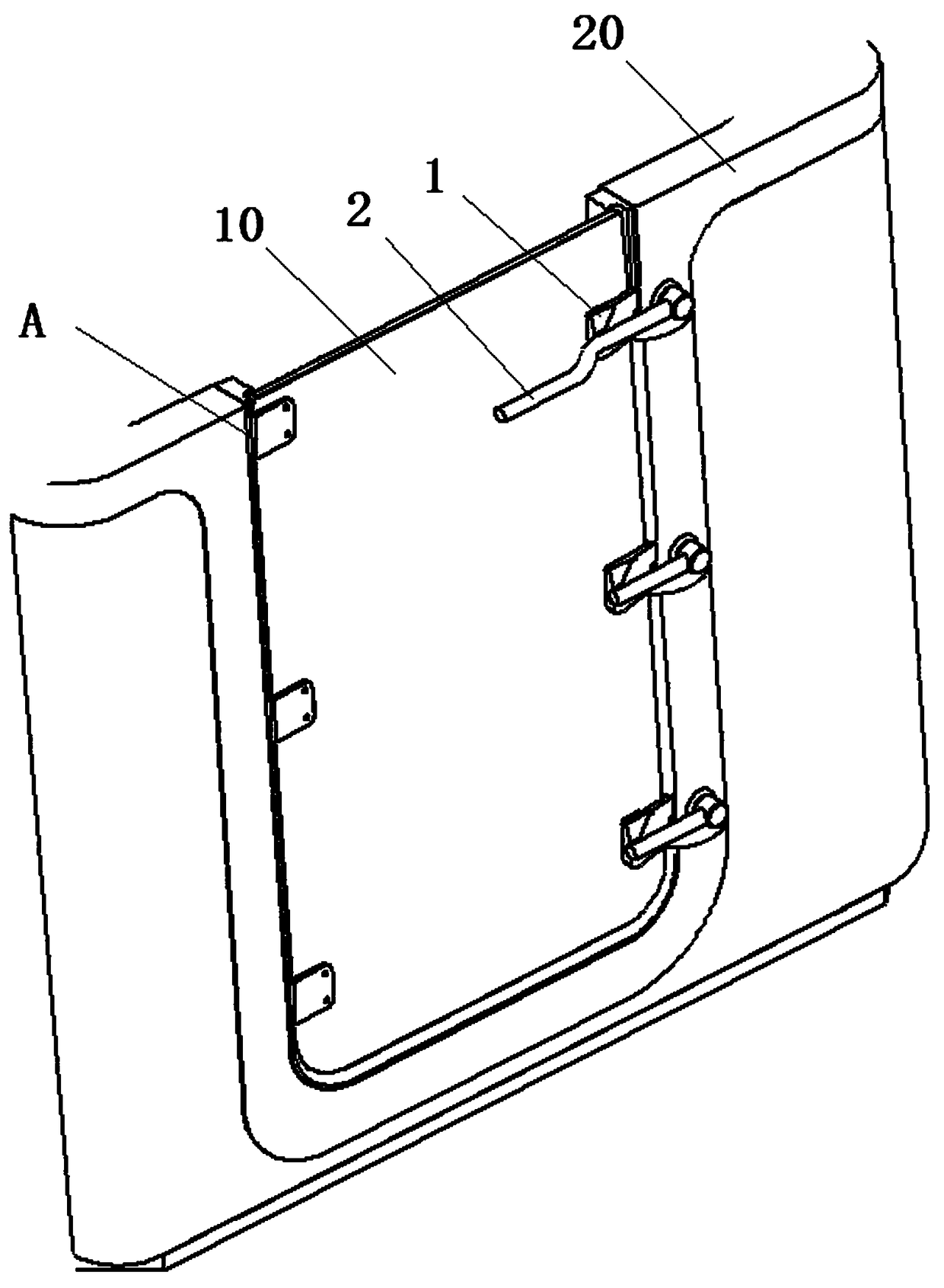
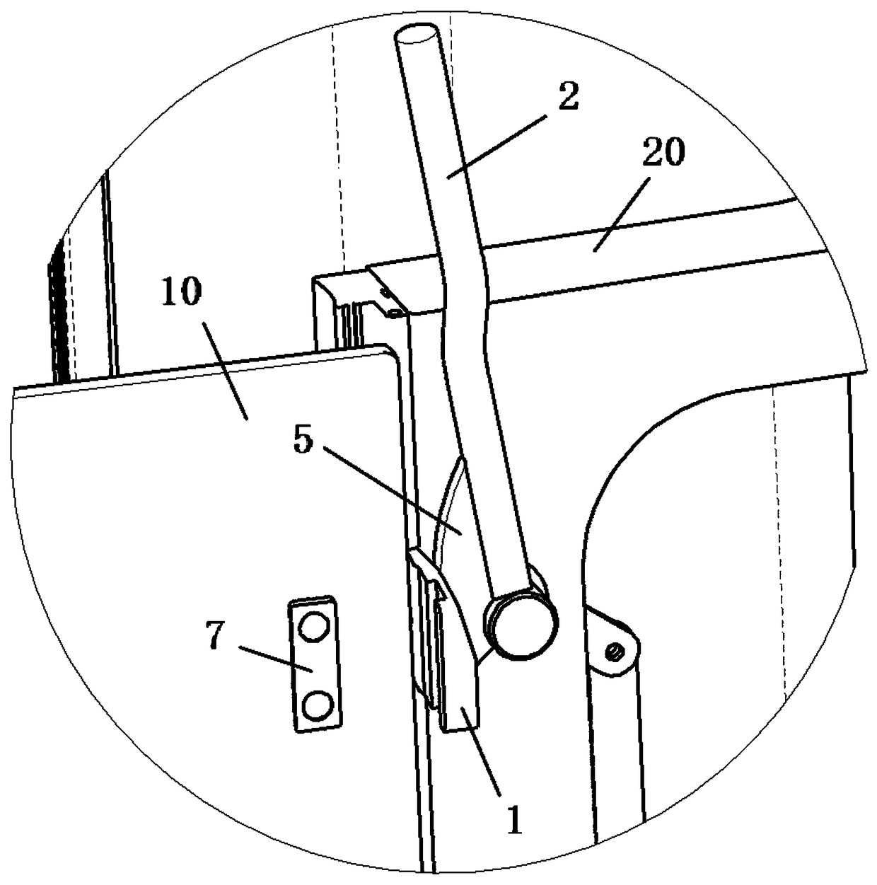
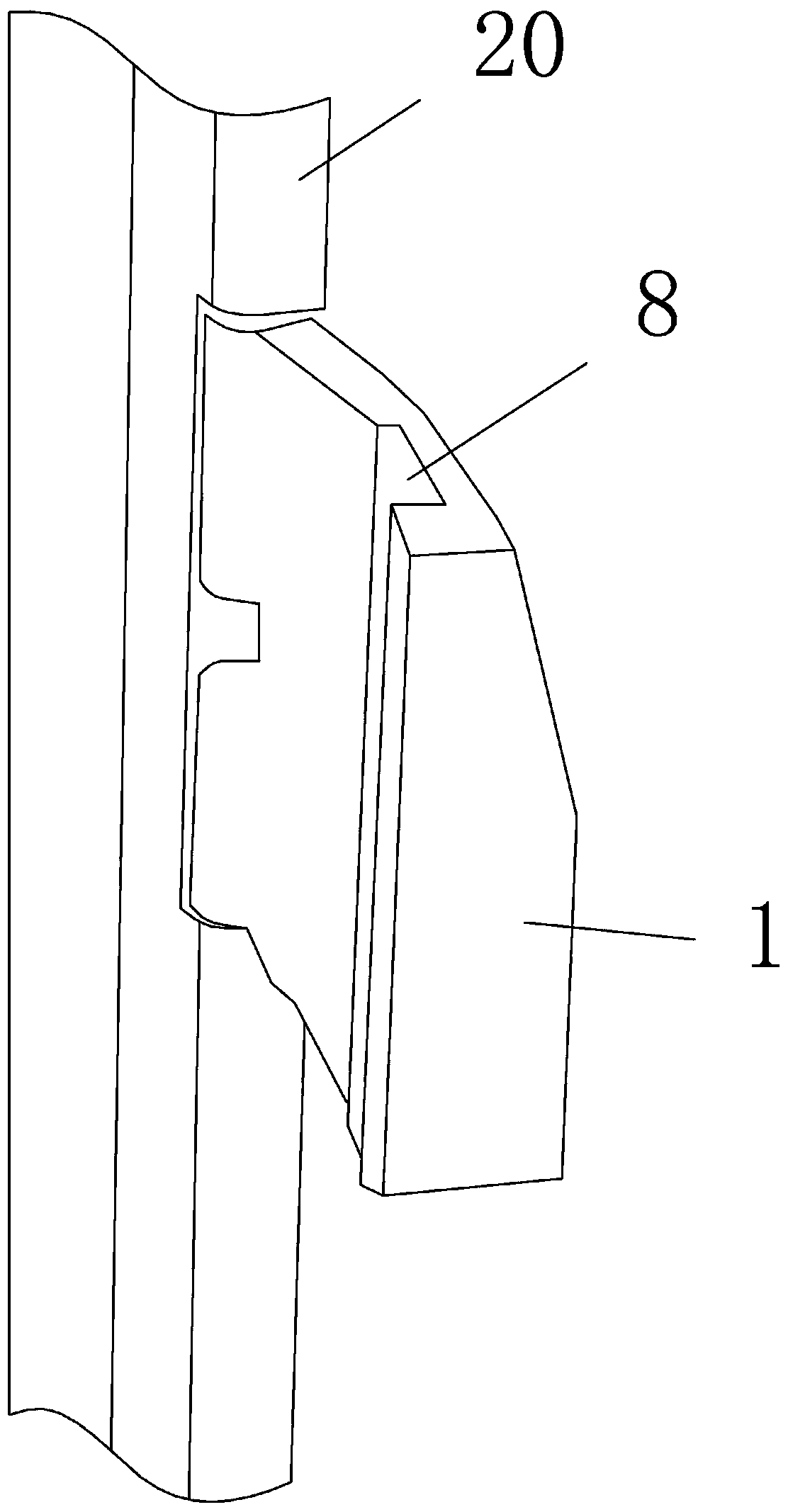
[0012] Such as Figure 1-6 shown.

[0013] One side of the door body 10 is hinged, and the door body can rotate around its hinge axis A. The other side of the door body opposite to the hinge axis can be closed with the door frame 20. Taking the door body in a closed state as an example, the door lock The device is installed between the door body and the door frame, including the locking block 1 and the driving rod 2 respectively hinged on the door frame, the rotation plane of the locking block is perpendicular to the door body, the rotation plane of the driving rod is parallel to the door body, and The locking block is arranged between the door body and the driving rod; the inner side of the locking block is against the outer side of the door body, and the outer side of the locking block is provided with a platform 3 parallel to the door body, and the platform faces the side of the driving rod The locking block is provided with an inclined surface 4 inclined to the outer surf...


PUM


Abstract

The invention provides a door lock device which comprises a positioning block, a locking block and a drive rod, wherein the positioning block is mounted on a door body; the locking block and the driverod are respectively hinged to a door frame; a platform, an oblique surface and a slope are arranged on the locking block; a drive sheet is mounted on the drive rod; during door locking, the drive rod is rotated, and the locking body rotates towards the door body through matching between the drive sheet and the oblique surface of the blocking block; then the locking block is driven under the drive of the drive rod and the slope of the locking block, and the rotation of the locking block can apply a locking force onto the door body till when the door body is tightly closed, the drive rod is propped against the platform of the locking block. The door lock device is simple in structure and convenient to operate, and the locking of the door body is extremely accurate and stable.

Description

technical field [0001] The present invention relates to a device for locking an openable door. Background technique [0002] A door is an entity installed at the entrance and exit of a building to divide a limited space, and a door lock is a device that locks the door in a closed state. The existing door lock device is generally installed on the door, and the door lock device is provided with a protruding dead bolt, and a concave lock groove is correspondingly set on the door frame, and the door is fixed on the door by inserting the dead bolt into the lock groove. on the door frame. At the same time, in order to drive the expansion and contraction of the dead bolt, a lock head connected to the dead bolt is installed in the door lock, and the key is inserted into the lock head to drive the dead bolt to move, but this kind of operation method is more troublesome. There will also be a pull rod or turntable connected to the deadbolt so that the movement of the deadbolt can be ...

Claims


Application Information

Patent Timeline
IPC IPC(8): E05C19/00
CPCE05C19/00
Inventor 弘伟杰陈显明李远宏
Owner 广州市绅士德实业有限公司
Learn More