
High-speed emergency rescue device

An emergency rescue, high-speed technology, applied in transportation and packaging, escalators, etc., can solve the problems of slow, impassable, and traffic jams for rescue vehicles, achieving valuable rescue time and avoiding interference.

Inactive Publication Date: 2018-08-31
张友琦
View PDF0 Cites 6 Cited by
  • Summary
  • Abstract
  • Description
  • Claims
  • Application Information

AI Technical Summary

Problems solved by technology

[0002] With the rapid development of my country's economy, the total mileage of national expressways is also increasing. As of 2017, the total mileage of expressways in my country has ranked first in the world. The important role and direct impact of expressways in the development of my country's national economy The proportion of regional gdp is getting bigger and bigger. For this reason, the smooth flow and safety of expressways have attracted more and more attention and attention from relevant departments and all walks of life. At the same time, it is known as the "life passage" of expressways. The emergency lane also has a rare emergency problem. When encountering a traffic accident on the expressway, it is difficult to deal with the accident vehicle in a short time, which is likely to cause traffic jams. Some vehicles that are eager to pass will occupy the emergency lane and cause rescue vehicles to pass. Slow or even impassable, delaying the most precious rescue time

Method used


Image

  • High-speed emergency rescue device
  • High-speed emergency rescue device
  • High-speed emergency rescue device

Examples


Embodiment Construction

[0023] Below in conjunction with specific embodiment, further illustrate the present invention, it should be understood that these embodiments are only used to illustrate the present invention and are not intended to limit the scope of the present invention, after reading the present invention, those skilled in the art will understand the various equivalent forms of the present invention All modifications fall within the scope defined by the appended claims of the present application.

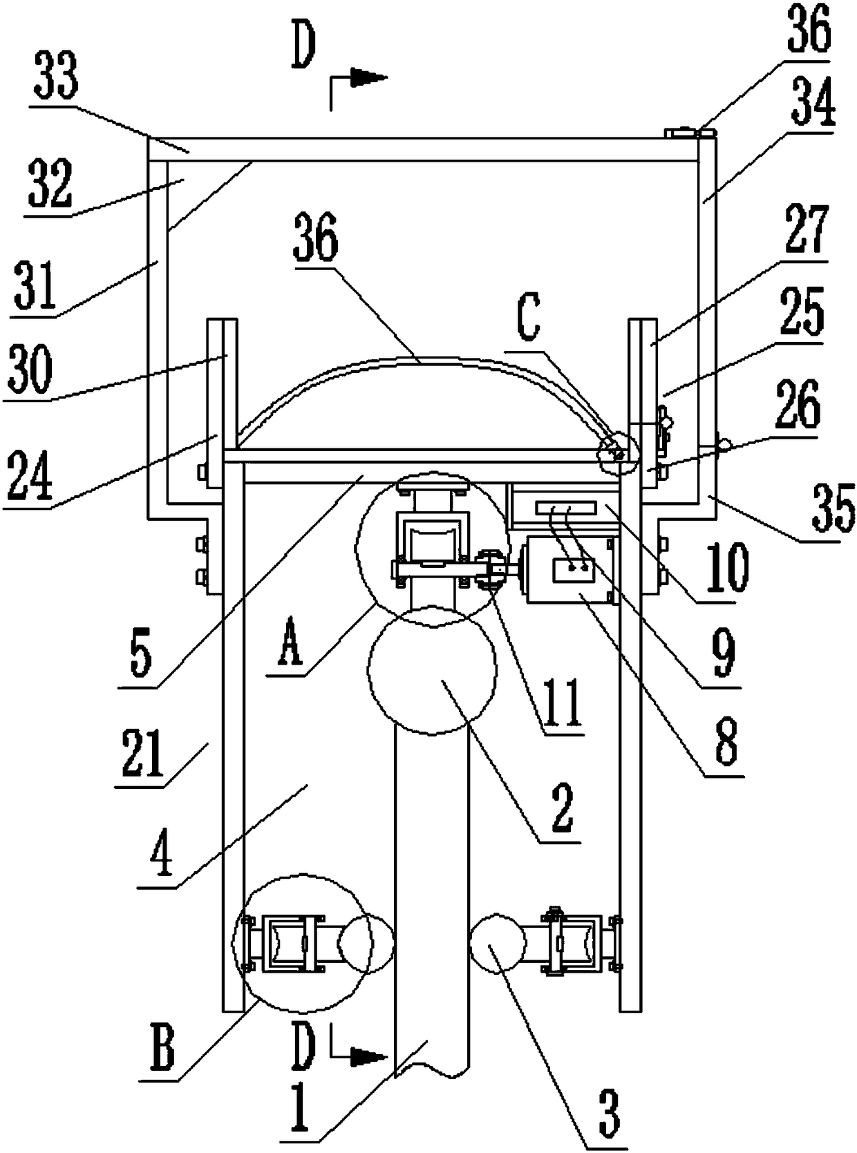
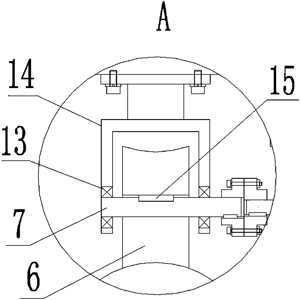
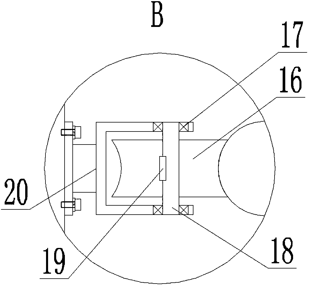
[0024] Such as Figure 1-7As shown, a high-speed emergency rescue device includes a guardrail 1, and a cylindrical main rail 2 is welded to the upper end of the guardrail along the length direction. The main rail is provided with an emergency rescue device. The emergency rescue device includes a U-shaped bracket 21, and the U-shaped bracket The U-shaped groove 4 is vertically facing downwards to frame the guardrail in it. The groove bottom plate 5 in the U-shaped groove is connected with a plur...


PUM


Abstract

The invention discloses a high-speed emergency rescue device. The high-speed emergency rescue devic comprises a guard bar. A primary guide rail is arranged at the upper end of the guard bar. An emergency rescue device is arranged on the primary guide rail, and comprises a U-shaped bracket. The U-shaped bracket faces downwards vertically to frame the guard bar therein. A plurality of rollers are connected to a groove bottom plate in the U-shaped groove, and are rotationally connected with the U-shaped bracket by means of rotating shafts. One of the rotating shafts is an lengthening shaft. The lengthening shaft is connected with the output end of a motor by means of a coupling. The motor is connected with a power source. Secondary guide rails are connected with the two sides of the middle ofthe guard bar. A plurality of guide wheels extend out of the U-shaped bracket, and are connected with the secondary guide rails in sequence in a rolling manner. The guide wheels are rotationally connected with the U-shaped bracket. Circular arc-shaped grooves matched with the secondary guide rails in shape are formed in the contact surfaces between the guide wheels and the secondary guide rails.A plurality of safety belts are arranged on the outer side of the groove bottom plate of the U-shaped bracket in the width direction. A wounded person is put on the emergency rescue device, and is sent out from a crowding area along the guard bar, so that interference of crowding on rescue is avoided.

Description

technical field [0001] The invention relates to the technical field of high-speed rescue, in particular to a transport device for transporting the wounded at high speed. Background technique [0002] With the rapid development of my country's economy, the total mileage of national expressways is also increasing. As of 2017, the total mileage of expressways in my country has ranked first in the world. The important role and direct impact of expressways in the development of my country's national economy The proportion of regional gdp is getting bigger and bigger. For this reason, the smooth flow and safety of expressways have attracted more and more attention and attention from relevant departments and all walks of life. At the same time, it is known as the "life passage" of expressways. The emergency lane also has a rare emergency problem. When encountering a traffic accident on the expressway, it is difficult to deal with the accident vehicle in a short time, which is likely ...

Claims


Application Information

Patent Timeline
IPC IPC(8): B66B21/00
CPCB66B21/00
Inventor 张友琦
Owner 张友琦
Learn More