An adjustable hoisting device for a serpentine tube panel and its hoisting method
A hoisting device and serpentine tube technology, which is applied in the field of adjustable hoisting devices for serpentine tube screens, can solve the problems of serpentine tube deformation, poor rigidity, and easy deformation, and achieve adaptability to spacing changes, stable and reliable connections, The effect of preventing deformation
- Summary
- Abstract
- Description
- Claims
- Application Information
AI Technical Summary
Problems solved by technology
Method used
Image
Examples
Embodiment 1
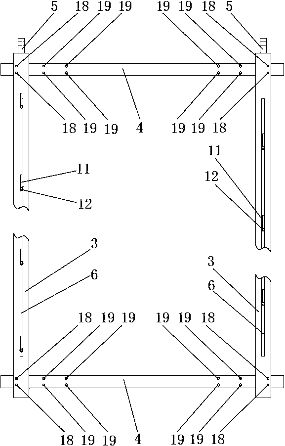
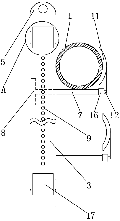
[0025] Such as Figures 1 to 3 , 8, an adjustable hoisting device for a serpentine tube panel, the serpentine tube panel consists of a number of straight pipes 1 and a number of elbows 2, including two left and right vertical beams 3 and two upper and lower beams 4, the four are fixed Connected into a rectangular frame, the top of the two vertical beams 3 has lifting lugs 5; the vertical beams 3 are rectangular steel, on the front end plate of the vertical beams 3 there is a guide groove 6 along its length direction, and a horizontal support rod is installed in the guide groove 6 7. The rear end of the horizontal support rod 7 extends into the vertical beam 3, and a bottom plate 8 is fixed at the rear end. The bottom plate 8 is in contact with the inner surface of the rear end plate of the vertical beam 3. The spacing between the end plates is adapted, the width of the guide groove 6 is adapted to the width of the horizontal support bar 7, and a number of adjustment holes 9 ar...
Embodiment 2
[0027] Such as image 3 and 5As shown, on the basis of Embodiment 1, the limit rod 11 is arc-shaped, and the inner arc surface of the limit rod 11 is used to fit and contact the outer surface of the straight pipe 1 of the serpentine tube panel. The lower end of the limit rod 11 There is a horizontal connecting rod 12, the rear end of the connecting rod 12 has a limiting circular platform 13, and the front end of the horizontal support rod 7 is provided with an axial mounting hole 14, the inner diameter of the mounting hole 14 matches the diameter of the limiting circular platform 13, A spring 15 and a locking sleeve 16 with internal threads are set on the connecting rod 12, and the front end of the horizontal support rod 7 has external threads. The front end of the rod 7 is threaded, the spring 15 is in a compressed state, one end of which is in contact with the limiting round table 13, and the other end is in contact with the locking sleeve 16, so that the inner arc surface ...
Embodiment 3
[0029] Such as Figures 1 to 4 , 6 and 7, on the basis of embodiment 2, the crossbeam 4 is I-beam, and the upper and lower ends of the end plates on both sides of the vertical beam 3 are provided with installation through holes 17, and the front end plate of the vertical beam 3 and the Two connection holes 18 are provided on the rear end plate corresponding to the positions of the installation through holes 17, and at least two groups of matching holes 19 are respectively provided on the left and right ends of the two end plates of the beam 4, and three groups of matching holes 19 are specifically set here. , that is, three sets of matching holes 19 are provided at the left end and right end of each end plate, each group includes two matching holes 19, and there is a distance between adjacent sets of matching holes 19, and the left and right ends of the beam 4 penetrate into the two vertical beams correspondingly 3 In the installation through hole 17 at the same end, the two m...
PUM
 Abstract
Description
Claims
Application Information
 - R&D
- Intellectual Property
- Life Sciences
- Materials
- Tech Scout
- Unparalleled Data Quality
- Higher Quality Content
- 60% Fewer Hallucinations
Browse by: Latest US Patents, China's latest patents, Technical Efficacy Thesaurus, Application Domain, Technology Topic, Popular Technical Reports.
© 2025 PatSnap. All rights reserved.Legal|Privacy policy|Modern Slavery Act Transparency Statement|Sitemap|About US| Contact US: help@patsnap.com


