A system for co-heating potassium hexafluoromanganate and antimony pentafluoride to produce fluorine gas and purify graphite

A technology of potassium hexafluoromanganate and antimony pentafluoride, which is applied in the direction of fluorine/hydrogen fluoride, fluorine, carbon compounds, etc., can solve problems such as ecological imbalance and ozone layer destruction, and achieve high environmental protection performance, good purification effect, and optimized equipment structure Effect

Active Publication Date: 2020-04-07
SINOSTEEL NEW MATERIAL ZHEJIANG
View PDF4 Cites 0 Cited by
  • Summary
  • Abstract
  • Description
  • Claims
  • Application Information

AI Technical Summary

Problems solved by technology

[0003] However, the freon used in the existing technology will destroy the ozone layer and cause ecological imbalance, and the user unit needs to approve the quota by the government

Method used


Image

  • A system for co-heating potassium hexafluoromanganate and antimony pentafluoride to produce fluorine gas and purify graphite
  • A system for co-heating potassium hexafluoromanganate and antimony pentafluoride to produce fluorine gas and purify graphite
  • A system for co-heating potassium hexafluoromanganate and antimony pentafluoride to produce fluorine gas and purify graphite

Examples


Embodiment 1

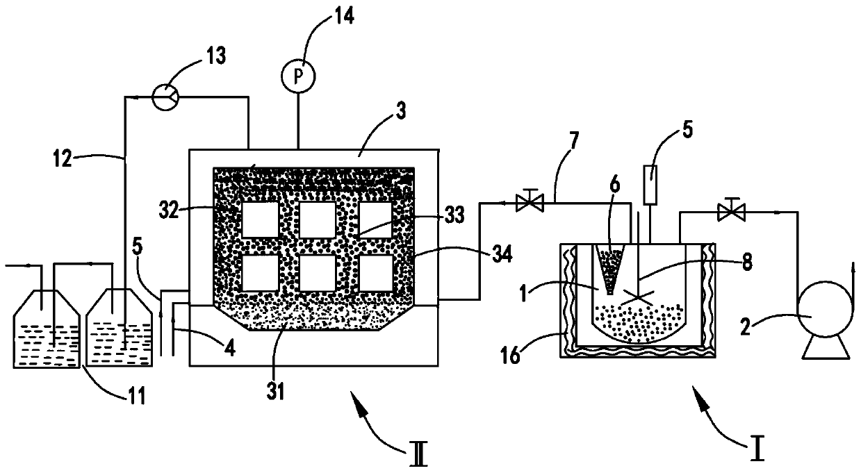
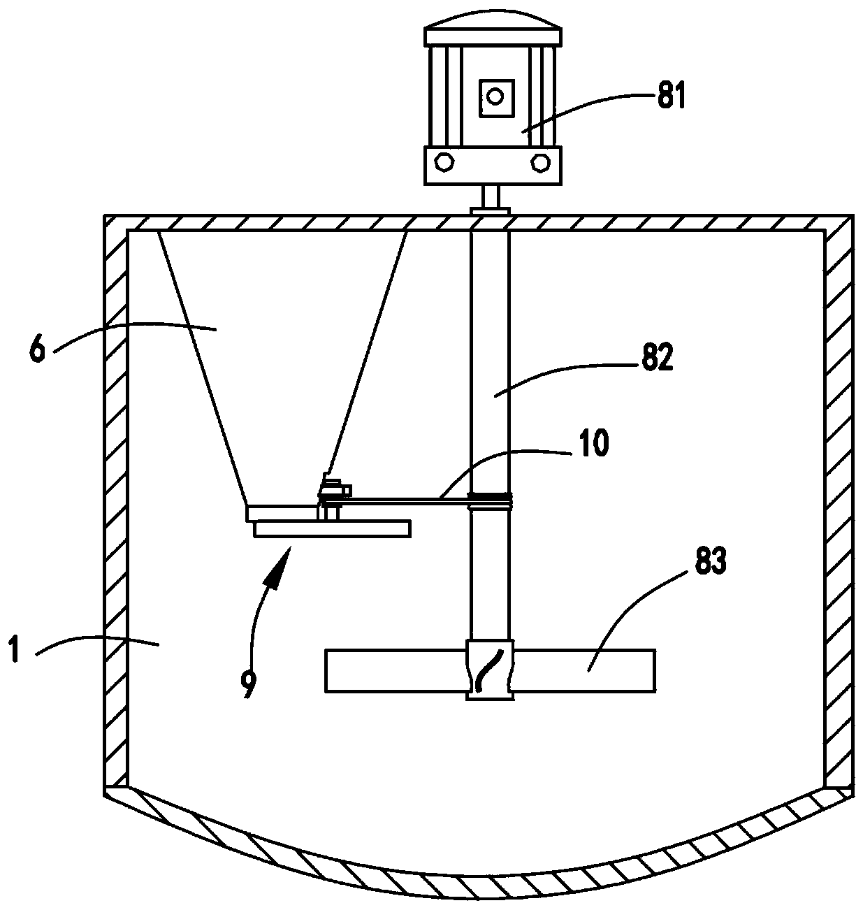
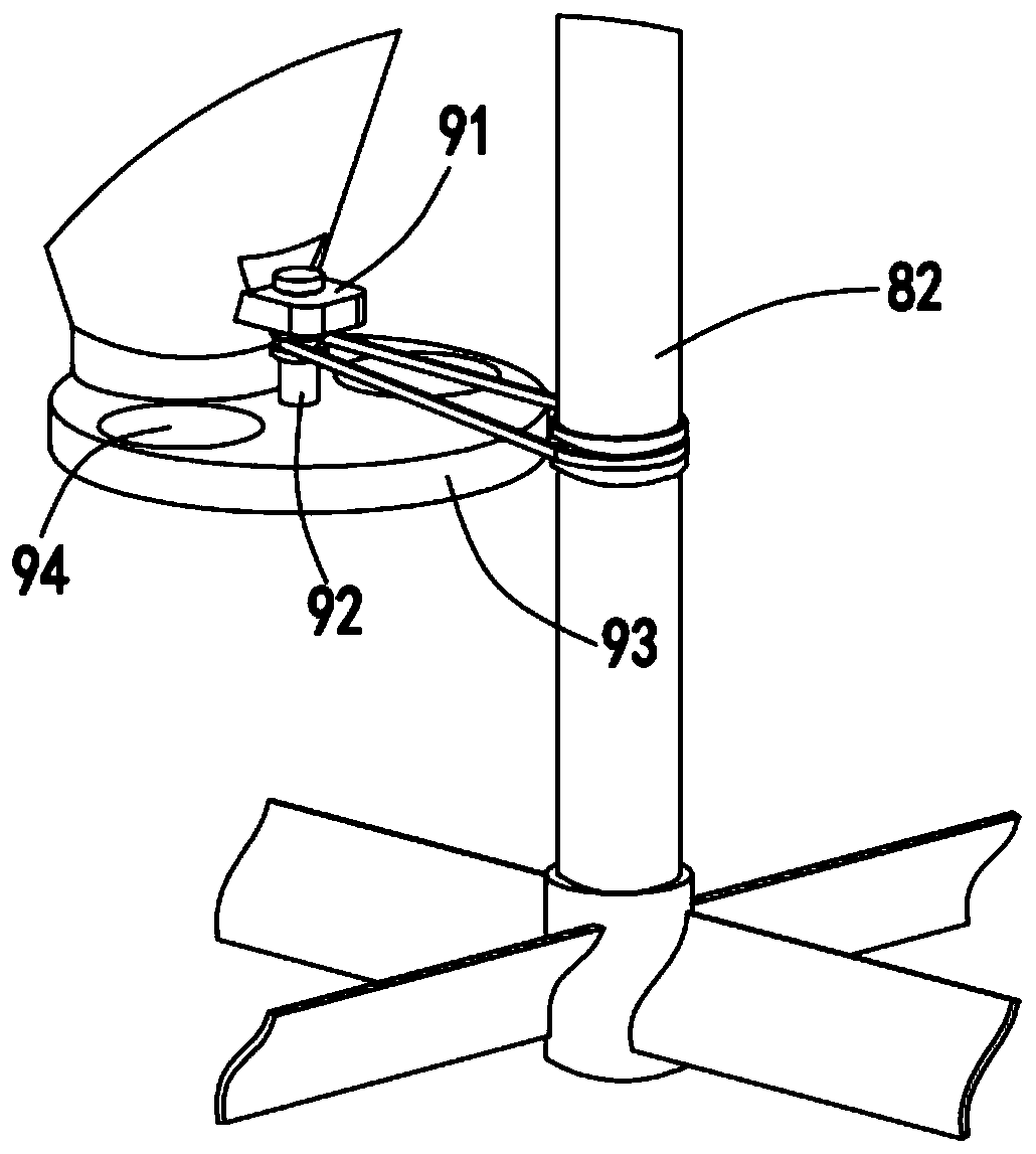
[0041] Such as figure 1 , figure 2 and image 3 As shown, the system for co-heating potassium hexafluoromanganate and antimony pentafluoride to produce fluorine gas to purify graphite includes a fluorine gas reaction unit I, and the fluorine gas reaction unit I includes:

[0042] A reactor 1 and a vacuum pump 2 for evacuating the inside of the reactor 1, a heater 3 for heating the reactor 1 is installed outside the reactor 1, and

[0043] Furnace body unit II, the furnace body unit II includes:

[0044] Furnace body 3, the bottom of described furnace body 3 is arranged with furnace bottom material 31, and graphite product is placed at furnace core 32, and graphite product is surrounded with resistance material 33, and the outer side of resistance material 33 is arranged with insulation material 34, and described One side of the furnace body 3 is provided with an inlet pipe a4 and an inlet pipe b5 for feeding nitrogen and chlorine gas into the furnace core 32 respectively. ...

Embodiment 2

[0055] Such as figure 2 As shown, as an improvement, one side of the furnace body 3 is also provided with an exhaust gas absorber 11, and the exhaust gas absorber 11 communicates with the furnace core 32 top of the furnace body 3 through the gas outlet pipe 12, and the gas outlet pipe 12 is provided with a Pump the gas in the furnace core 32 to the gas pump 13 of the tail gas absorber 11;

[0056] The top of the furnace body 3 is also provided with a pressure gauge 14 for monitoring the internal pressure of the furnace core 32 .

[0057] It should be noted that the tail gas absorber 11 is composed of several sodium hydroxide solution absorbers, and the fluorine gas and sodium hydroxide are removed by reaction, and the equation is 2F 2 +4NaOH→NaF+2H 2 O+O 2 , The gasified sodium fluoride is dissolved in the aqueous solution. In this embodiment, the waste gas generated by graphitization and purification is avoided by setting the tail gas absorber to be directly discharged in...


PUM


Abstract

The invention relates to a system for purifying graphite with a hexafluoro-potassium manganate and antimony pentafluoride co-heating generated fluorine gas. The system comprises a fluorine gas reaction unit I and a fluorine gas reaction unit II, wherein the fluorine gas reaction unit I comprises a reactor and a vacuum pump for vacuuming the reactor; a heater for heating the reactor is mounted outside the reactor; the fluorine gas reaction unit II comprises a furnace body; a furnace substrate is arranged at the bottom of the furnace body; a graphite product is placed beside a furnace core; a resistance material is arranged around the graphite product; a heat-preservation material is arranged outside the resistance material; a gas inlet tube a and a gas inlet tube b for introducing nitrogenand chlorine into the furnace core respectively are arranged on one side of the furnace body; the reactor is used for implementing reactions to generate a fluorine gas; the fluorine gas is introducedinto the bottom of the furnace core to remove impurity elements in the graphite product. By adopting the system, a chemical reactor is arranged on one side of a graphitization furnace, the graphite inside the graphitization furnace is purified with the hexafluoro-potassium manganate and antimony pentafluoride co-heating generated fluorine gas inside the reactor, and the problem of environment pollution caused when Freon is used can be avoided.

Description

Technical field: [0001] The invention relates to the technical field of graphite purification, in particular to a system for purifying graphite by co-heating potassium hexafluoromanganate and antimony pentafluoride to produce fluorine gas. Background technique: [0002] Existing technical status: the current purified graphite is purified by gas heat in graphitization, and most metal halides have relatively low melting and boiling points, especially some high-boiling impurities such as boron, vanadium, molybdenum, silicon, etc. must pass through Chlorination and fluorination can be removed. During graphitization and purification, nitrogen is generally introduced when the temperature of the furnace core reaches a certain level, the air in the furnace core is removed, and then chlorine gas is introduced. The high boiling point impurities form compounds and then reduce the boiling point and discharge with the gas. [0003] However, the freon used in the prior art will destroy ...

Claims


Application Information

Patent Timeline
Patent Type & Authority Patents(China)
IPC IPC(8): C01B32/215C01B7/20
CPCC01B7/20C01B32/215
Inventor 杨辉黄岱沈华平许汉春
Owner SINOSTEEL NEW MATERIAL ZHEJIANG
Why Eureka
Try Eureka