Novel hoop

A new type of hoop technology, applied in the direction of connecting components, mechanical equipment, friction-clamped detachable fasteners, etc., can solve the problems of increased cost and unfavorable on-site use, and achieves reduced carrying weight, convenient use, and improved on-site performance. The effect of management efficiency

Inactive Publication Date: 2018-09-04
CHENGDU JUNSHUO RUIZHI INFORMATION TECH CO LTD
View PDF0 Cites 4 Cited by
  • Summary
  • Abstract
  • Description
  • Claims
  • Application Information

AI Technical Summary

Problems solved by technology

[0004] In order to solve the problem that the existing hoops are either arc-shaped or square, in the actual use process, the constructor needs to reserve two different hoops, which increases the cost and also needs to carry and manage two kinds of hoops during the actual installation process. Working with different hoops is not conducive to field use. The invention provides a new type of hoop

Method used


Image

  • Novel hoop
  • Novel hoop
  • Novel hoop

Examples


Embodiment 1

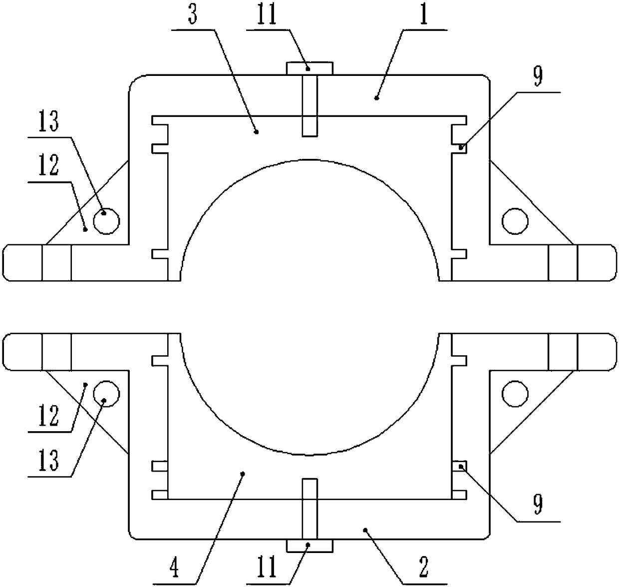
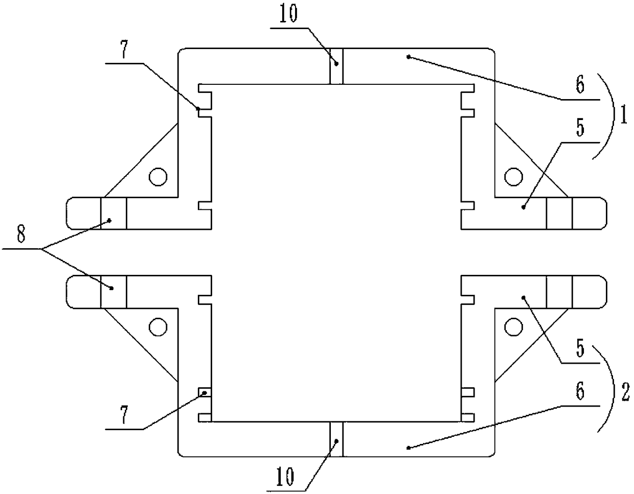
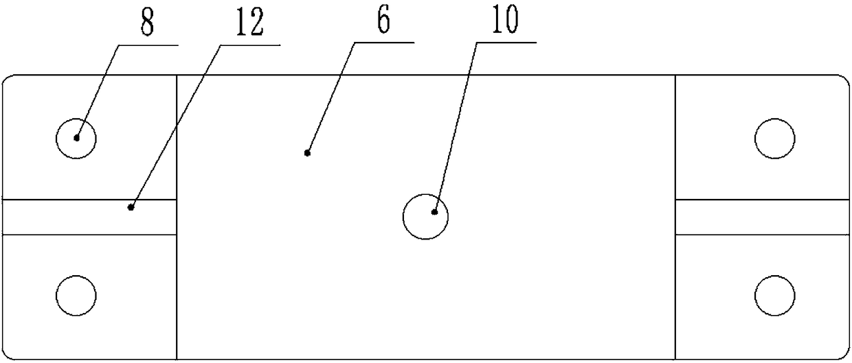
[0030] like Figure 1-2 As shown, a new hoop includes an upper half hoop 1, a lower half hoop 2, an upper half insert 3 and a lower half insert 4, and both the upper half hoop 1 and the lower half hoop 2 include mounting ears 5 and the hoop body 6 with a U-shaped cross section, the mounting ears 5 are symmetrically arranged on both sides of the opening of the hoop body 6; both sides of the inner wall of the hoop body 6 are symmetrically provided with a number of card slots 7; the upper half The mounting ears 5 of the hoop 1 and the lower half hoop 2 are provided with corresponding bolt holes 8, and the upper half hoop 1 and the lower half hoop 2 move through the bolts provided in the corresponding bolt holes 8. Connection; a reinforcing plate 12 is provided between the hoop body 6 and the mounting ear 5 , and a through hole 13 is provided on the reinforcing plate 12 .

[0031] The cross-section of the upper half insert 3 and the lower half insert 4 is arch bridge-shaped, and ...

Embodiment 2

[0040] like Figure 1-3 As shown, this implementation is further optimized on the basis of Embodiment 1. This embodiment focuses on the improvements compared with Embodiment 1, and the similarities will not be repeated. In this embodiment, the upper half of the hoop 1 The top wall of the hoop body 6 and the bottom wall of the hoop body 6 of the lower half hoop 2 are provided with through threaded holes 10, and the top of the upper half inlay 3 and the bottom of the lower half inlay 4 are provided with The screw holes corresponding to the screw holes 10 are connected by fixing screws 11 between the screw holes 10 and the screw holes. The hoop body 6 of the upper half hoop 1 and the upper half insert 3 and the hoop body 6 of the lower half hoop 2 and the lower half insert 4 can be more stably connected by fixing the screw 11 .


PUM


Abstract

The invention discloses a novel hoop, and belongs to the technical field of iron accessories. The novel hoop is used for solving the problems that an existing hoop is arc or square, a constructor needs to prepare two kinds of different hoops for use in the actual using process, the cost is increased, and on-site use is not facilitated. The novel hoop comprises an upper half hoop, a lower half hoop, an upper half insert and a lower half insert, and the upper half hoop and the lower half hoop each comprise installing lugs and a hoop body with a U-shaped cross section, wherein the installing lugsare symmetrically arranged on the two sides of the opening of the hoop body; a plurality of clamping grooves are symmetrically formed in the two sides of the inner wall of each hoop body, the installing lugs of the upper half hoop and the lower half hoop are provided with corresponding bolt holes, and the upper half hoop and the lower half hoop are movably connected through bolts arranged in thecorresponding bolt holes; and cross sections of the upper half insert and the lower half insert are arch, clamping blocks are symmetrically arranged on the two sides of the upper half insert and the lower half insert, the upper half insert and the upper half hoop are movably connected through the corresponding clamping blocks and the corresponding clamping grooves, and the lower half insert and the lower half hoop are movably connected through the corresponding clamping blocks and the corresponding clamping grooves.

Description

technical field [0001] The invention relates to the technical field of iron accessories, in particular to a novel hoop. Background technique [0002] Iron accessories are commonly known as structural (attachment) parts for power line transmission and transformation, and are non-standard parts produced according to the special requirements of users. Including cross arms, booms and hoops, etc. [0003] A hoop is a component that hugs or hoops another material with one material, and it belongs to a fastener. In the process of erecting power lines, hoops are used quite frequently, such as fixing distribution boxes and cross arms on utility poles and erecting power lines on utility poles. At present, in the power line erection project, the direction of the power line is generally determined by the position of the pole, and the hoop is usually fastened on the pole, but the existing hoop is either arc-shaped or square. , There are round and square poles, and the constructor need...

Claims


Application Information

Patent Timeline
Patent Type & Authority Applications(China)
IPC IPC(8): F16B2/06
Inventor 张德彬
Owner CHENGDU JUNSHUO RUIZHI INFORMATION TECH CO LTD
Why Eureka
Try Eureka