A displacement device for welding the heat exchange tube of the boiler body and the drum

A boiler body and displacement device technology, applied in welding equipment, auxiliary equipment, auxiliary welding equipment, etc., can solve the problems of harsh working environment, many connecting welds, and low work efficiency, and achieve broad application prospects and high degree of automation , Guarantee the effect of weld quality

Active Publication Date: 2019-09-17
XIANGTAN UNIV
View PDF14 Cites 0 Cited by
  • Summary
  • Abstract
  • Description
  • Claims
  • Application Information

AI Technical Summary

Problems solved by technology

[0002] Boilers are high-temperature and high-pressure equipment, and their manufacturing quality requirements are relatively high. There are many welding seams connecting the drum and heat exchange tubes in the boiler body, and there are a large number of rings that need to be welded along the circumference of the end of the heat exchange tubes in the boiler drum. Welding seams, due to the small diameter of the general drum, the welding environment of the welder in the semi-closed space is harsh, and the physical and mental health of the welder is affected by the high labor intensity and long working hours, resulting in low work efficiency and difficult to guarantee welding quality. It is difficult for enterprises to recruit workers and other problems, which seriously affects work efficiency and economic benefits of enterprises

Method used


Image

  • A displacement device for welding the heat exchange tube of the boiler body and the drum
  • A displacement device for welding the heat exchange tube of the boiler body and the drum
  • A displacement device for welding the heat exchange tube of the boiler body and the drum

Examples


Embodiment Construction

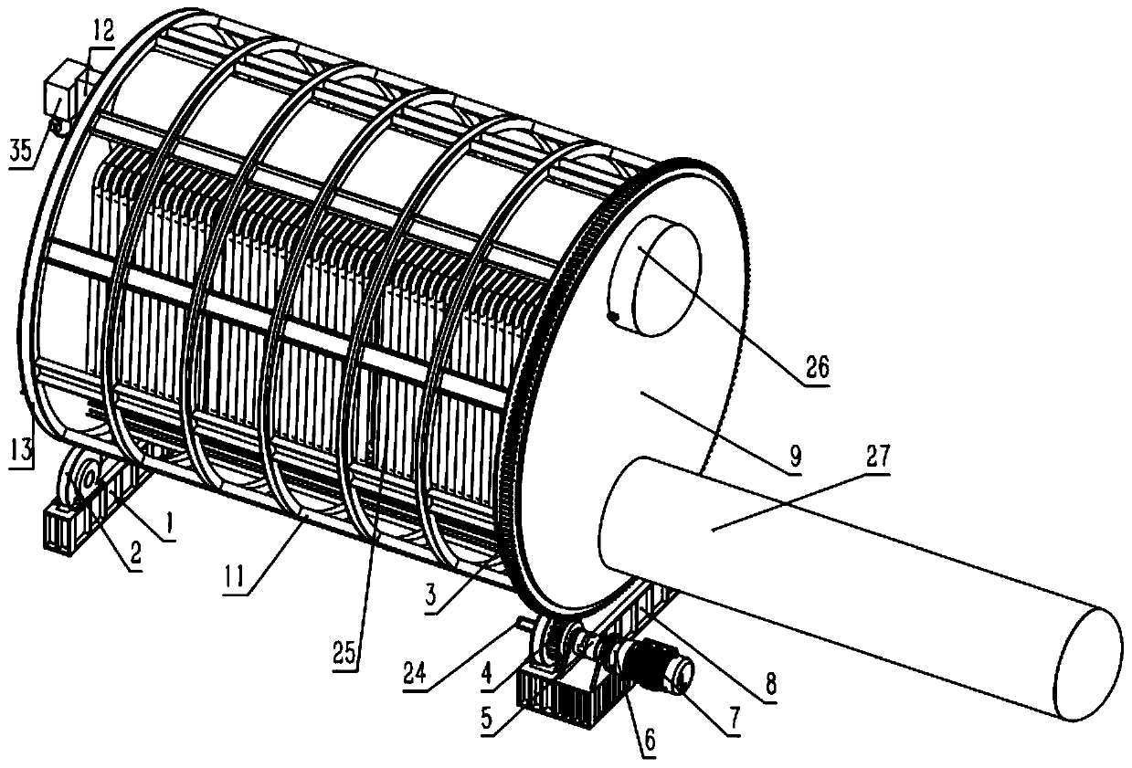
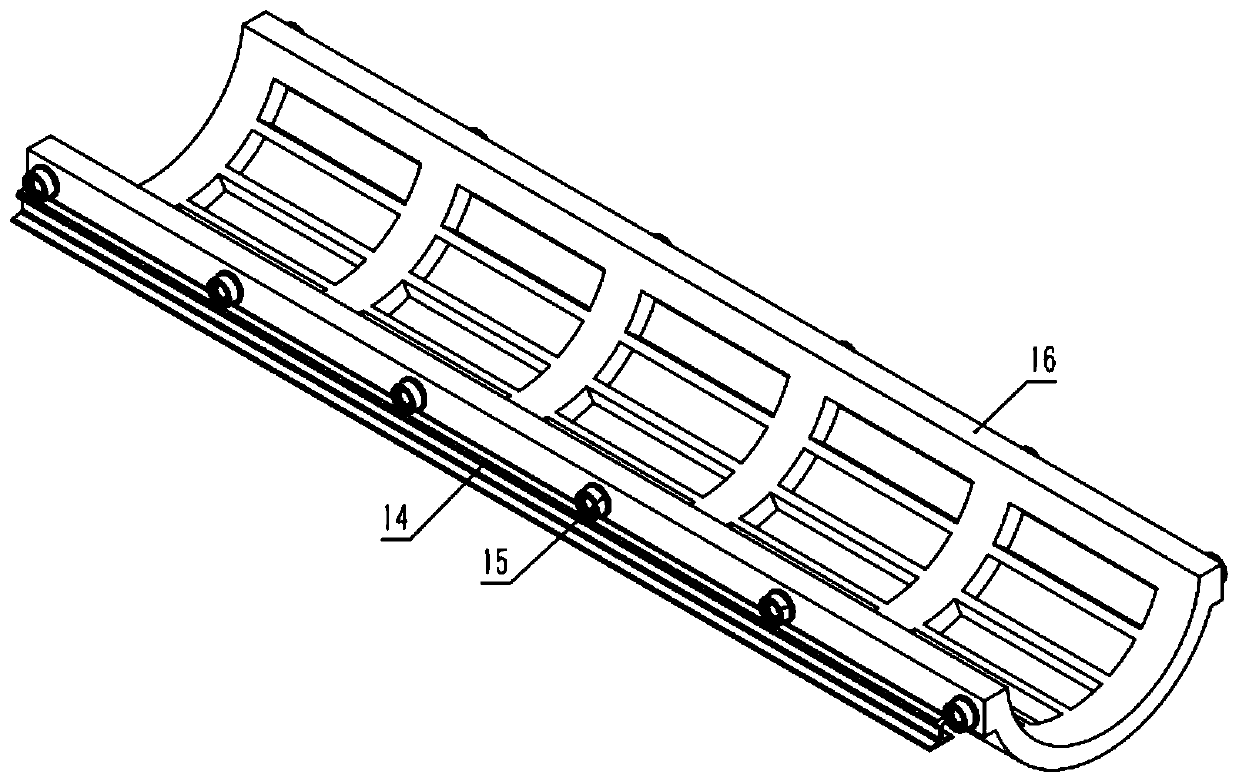
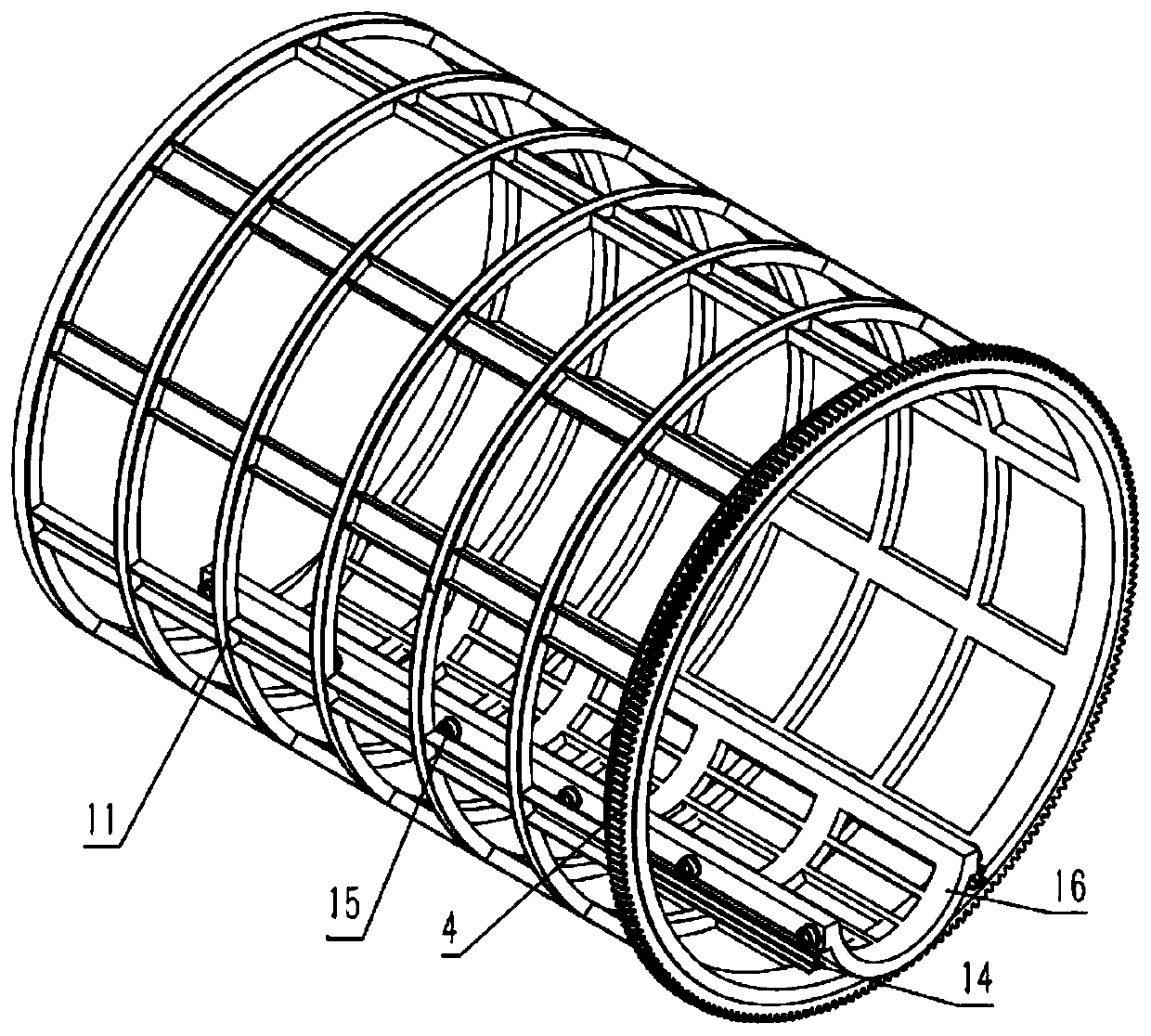
[0021] The present invention will be further described in detail below in conjunction with the accompanying drawings and embodiments.

[0022] see figure 1 , figure 2 , image 3 , this example includes a figure 2 The trolley shown, the main body 16 of the trolley is an arc-shaped groove, which is welded by steel plates and profiles, and the lower drum 26 is fixedly installed in the arc-shaped groove; The wheel 15 of rim, dolly is placed on two steel rails 14 on the base by wheel 15 and can move along steel rail 14. It also includes a cage-shaped tumbler 11, in which two parallel rails are fixed, the height and spacing of which are the same as the two rails 14 on the base; the left and right ends of the tumbler 11 are respectively provided with a supporting ring 13 The two support rings 13 are fixedly connected by welding mesh shaped steel; the outer end of the right end support ring 13 is also provided with a large gear 3, and the bottom of the right end of the rotating ...


PUM


Abstract

The invention discloses a position changing device for welding of a heat exchanging pipe and a boiler barrel of a boiler body. The position changing device for welding of the heat exchanging pipe andthe boiler barrel of the boiler body mainly comprises a trolley and a rotating cage; two steel rails are fixed in the rotating cage; the left and right ends are each provided with a supporting ring; alarge gear is arranged at the right end; a driving roller frame is arranged at the bottom of the right end; a driven roller frame is arranged at the bottom of the left end; the left and right ends are further provided with end covers; a round hole corresponding to the boiler barrel of the boiler body is formed in each end cover; after assembling of the boiler body is completed on the trolley, thetrolley and the boiler body are pulled to enter the rotating cage through a winch, and then the end covers are installed; a welding gun frame is fixed to the left end cover of the rotating cage, anda welding gun is fixed to each of the two ends of the welding gun frame; and the welding guns stretch into the boiler barrel. A motor is used for driving a small gear on the driving roller frame to drive the large gear, the rotating cage is made to rotate, position changing of the boiler body is achieved, an opening of the heat exchanging pipe vertically faces upwards, and the end portion is in ahorizontal state; and meanwhile, the motor is used for driving the welding gun frame to make the welding guns face downwards, and due to the composite movement of the above two parts, a workpiece weldjoint is made to be in a horizontal welding state.

Description

technical field [0001] The invention belongs to an auxiliary device for boiler welding operation, in particular to a device used to drag the boiler body to move the heat exchange tube and the inner wall of the boiler drum to the desired welding seam when the heat exchange tube and the boiler drum are welded. Positioning device for welding operations. Background technique [0002] The boiler is a high-temperature and high-pressure equipment, and its manufacturing quality requirements are high. There are many welding seams connecting the drum and the heat exchange tube in the boiler body, and there are a large number of rings that need to be welded along the circumference of the end of the heat exchange tube in the boiler drum. For welding seams, due to the small diameter of the general drum, the welder is in a semi-enclosed space and the welding operation environment is harsh. Due to the high labor intensity and long working hours, it will affect the physical and mental healt...

Claims


Application Information

Patent Timeline
Patent Type & Authority Patents(China)
IPC IPC(8): B23K37/047B23K37/02B23K37/04
Inventor 张大兵彭智力刘佳宝张田力
Owner XIANGTAN UNIV
Why Eureka
Try Eureka